|
|
| transputer architecture _____________________________________________________________________ |
| INMOS July 1987 |
This manual describes the architecture of the transputer family of products. The first section gives a brief summary of the major features of the transputer architecture and a rationale. The second section gives an overview of the programming model. The third section describes the aspects of the transputer which are common to all members of the transputer family.
Other information relevant to all transputer products is contained in the occam programming manual (supplied with INMOS software products and available as a separate publication), and the transputer development system manual (supplied with the development system).
The examples given in this manual are outline design studies and are included to illustrate various ways in which transputers can be used. The examples are not intended to provide accurate application designs.
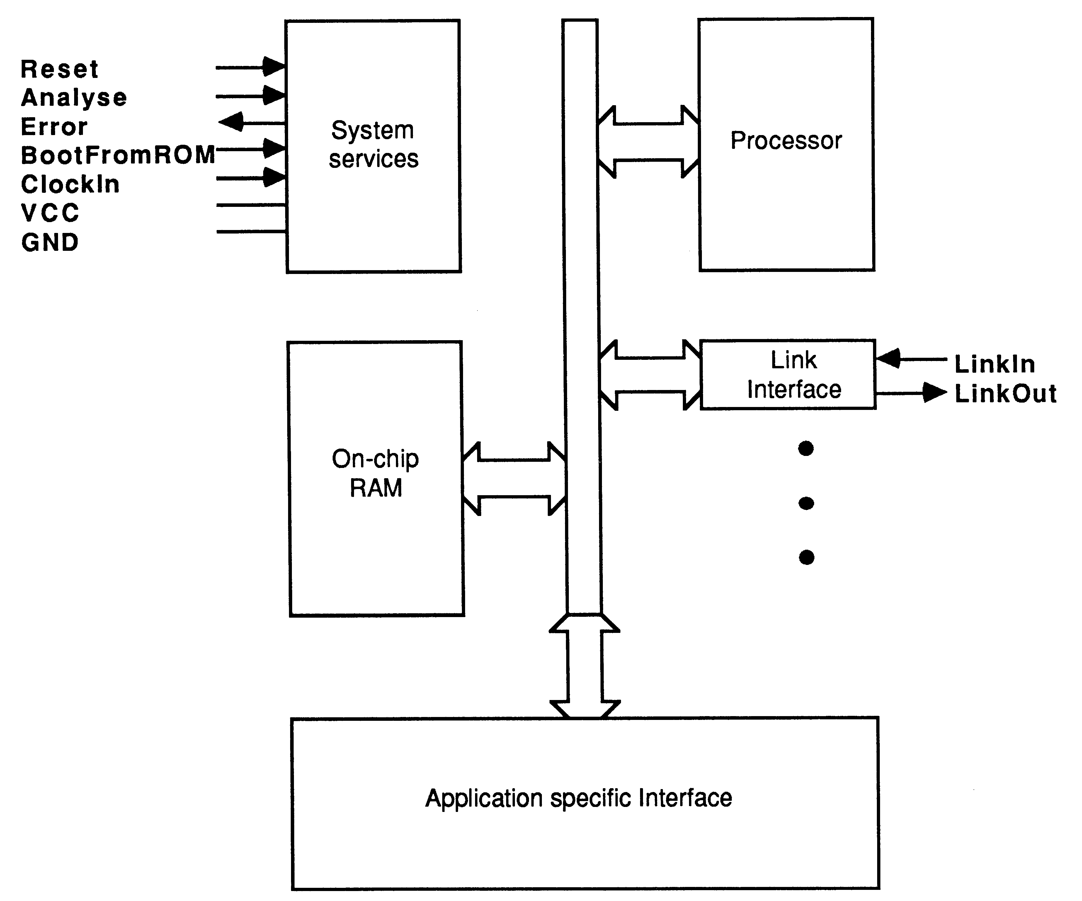
A transputer is a microcomputer with its own local memory and with links for connecting one transputer to another transputer.
The transputer architecture defines a family of programmable VLSI components. The definition of the architecture falls naturally into the logical aspects which define how a system of interconnected transputers is designed and programmed, and the physical aspects which define how transputers, as VLSI components, are interconnected and controlled.
A typical member of the transputer product family is a single chip containing processor, memory, and communication links which provide point to point connection between transputers. In addition, each transputer product contains special circuitry and interfaces adapting it to a particular use. For example, a peripheral control transputer, such as a graphics or disk controller, has interfaces tailored to the requirements of a specific device.
A transputer can be used in a single processor system or in networks to build high performance concurrent systems.
Transputers can be programmed in most high level languages, and are designed to ensure that compiled programs will be efficient. Where it is required to exploit concurrency, but still to use standard languages, occam can be used as a harness to link modules written in the selected languages.
To gain most benefit from the transputer architecture, the whole system can be programmed in occam. This provides all the advantages of a high level language, the maximum program efficiency and the ability to use the special features of the transputer.
Occam provides a framework for designing concurrent systems using transputers in just the same way that boolean algebra provides a framework for designing electronic systems from logic gates. The system designer’s task is eased because of the architectural relationship between occam and the transputer. A program running in a transputer is formally equivalent to an occam process, so that a network of transputers can be described directly as an occam program.
The transputer architecture simplifies system design by the use of processes as standard software and hardware building blocks.
An entire system can be designed and programmed in occam, from system configuration down to low level I/0 and real time interrupts.
The software building block is the process. A system is designed in terms of an interconnected set of processes. Each process can be regarded as an independent unit of design. It communicates with other processes along point-to-point channels. Its internal design is hidden, and it is completely specified by the messages it sends and receives. Communication between processes is synchronized, removing the need for any separate synchronisation mechanism.
Internally, each process can be designed as a set of communicating processes. The system design is therefore hierarchically structured. At any level of design, the designer is concerned only with a small and manageable set of processes.
Occam is based on these concepts, and provides the definition of the transputer architecture from the logical point of view (see section 2).
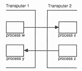
Processes can be implemented in hardware. A transputer, executing an occam program, is a hardware process. The process can be independently designed and compiled. Its internal structure is hidden and it communicates and synchronizes with other transputers via its links, which implement occam channels.
Other hardware implementations of the process are possible. For example, a transputer with a different instruction set may be used to provide a different cost/performance trade-off. Alternatively, an implementation of the process may be designed in terms of hard-wired logic for enhanced performance.
The ability to specify a hard-wired function as an occam process provides the architectural framework for transputers with specialized capabilities (e.g., graphics). The required function (e.g., a graphics drawing and display engine) is defined as an occam process, and implemented in hardware with a standard occam channel interface. It can be simulated by an occam implementation, which in turn can be used to test the application on a development system.
A transputer can be programmed to perform a specialized function, and be regarded as a ’black box’ thereafter. Some processes can be hard-wired for enhanced performance.
A system, perhaps constructed on a single chip, can be built from a combination of software processes, preprogrammed transputers and hardware processes. Such a system can, itself, be regarded as a component in a larger system.
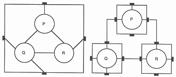
The architecture has been designed to permit a network of programmable components to have any desired topology, limited only by the number of links on each transputer. The architecture minimizes the constraints on the size of such a system, and the hierarchical structuring provided by occam simplifies the task of system design and programming.
The result is to provide new orders of magnitude of performance for any given application, which can now exploit the concurrency provided by a large number of programmable components.
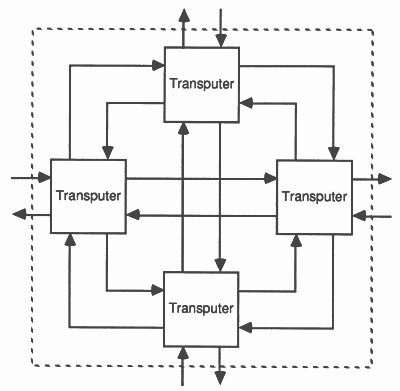
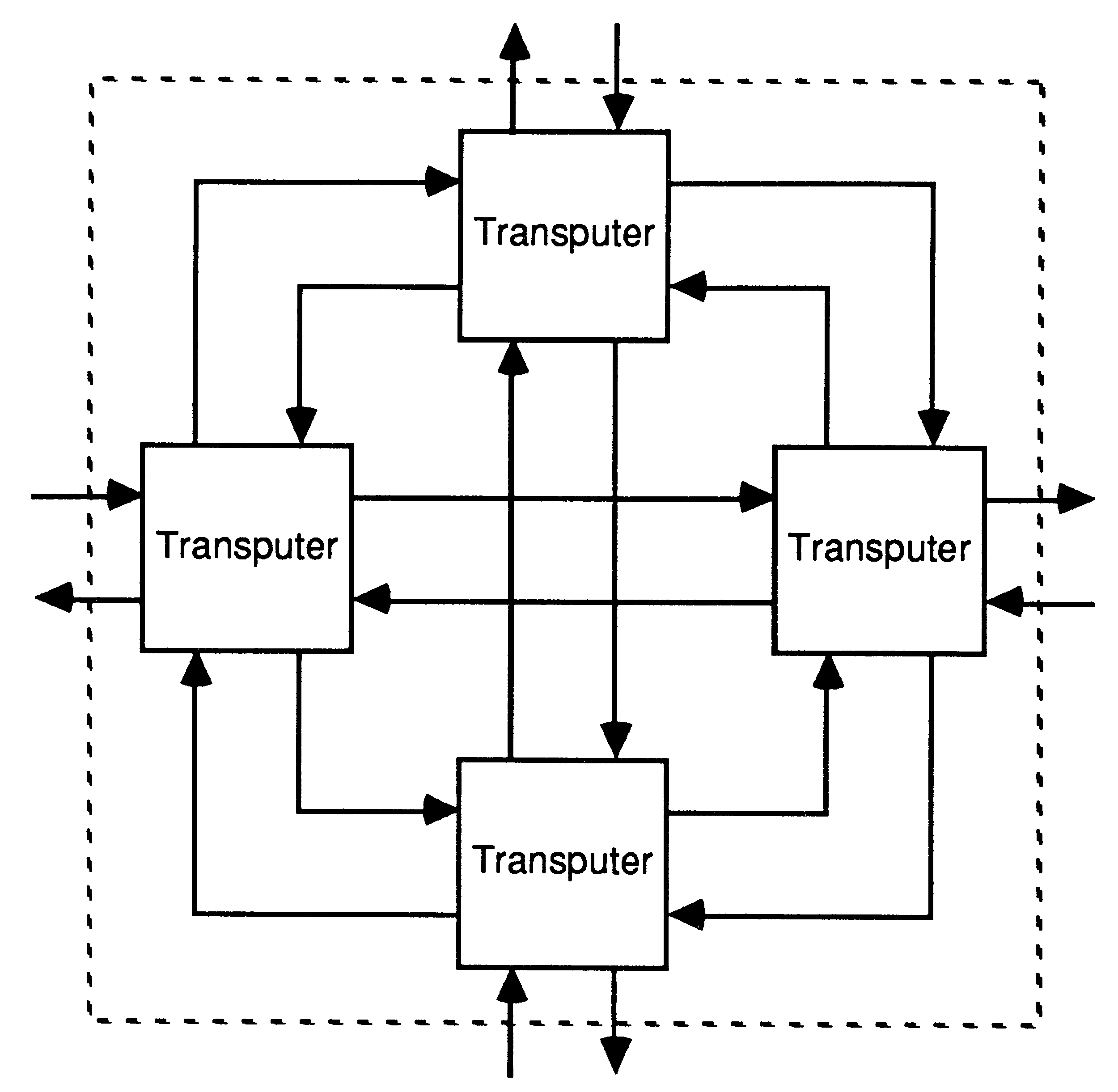
The transputer architecture simplifies system design by using point to point communication links. Every member of the transputer family has one or more standard links, each of which can be connected to a link of some other component. This allows transputer networks of arbitrary size and topology to be constructed.
Point to point communication links have many advantages over multi-processor buses:
There is no contention for the communication mechanism, regardless of the number of transputers in the system.
There is no capacitive load penalty as transputers are added to a system.
The communications bandwidth does not saturate as the size of the system increases. Rather, the larger the number of transputers in the system, the higher the total communications bandwidth of the system. However large the system, all the connections between transputers can be short and local.
Each transputer in a system uses its own local memory. Overall memory bandwidth is proportional to the number of transputers in the system, in contrast to a large global memory, where the additional processors must share the memory bandwidth.
Because memory interfaces are not shared, and are separate from the communications interfaces, they can be individually optimized on different transputer products to provide high bandwidth with the minimum of external components.
To provide synchronised communication, each message must be acknowledged. Consequently, a link requires at least one signal wire in each direction.
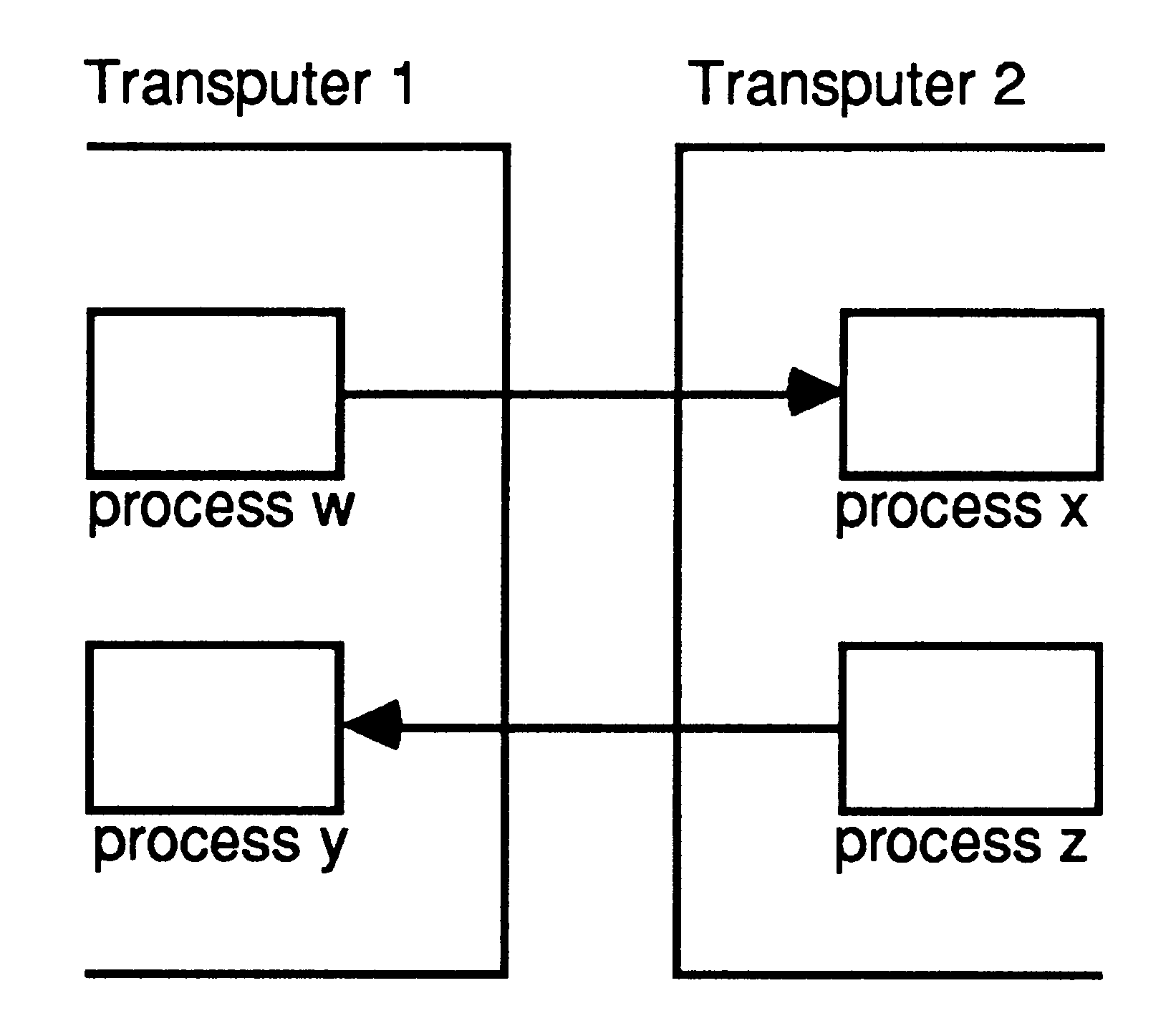
A link between two transputers is implemented by connecting a link interface on one transputer to a link interface on the other transputer by two one-directional signal lines, along which data is transmitted serially.
The two signal wires of the link can be used to provide two occam channels, one in each direction. This requires a simple protocol. Each signal line carries data and control information.
The link protocol provides the synchronized communication of occam. The use of a protocol providing for the transmission of an arbitrary sequence of bytes allows transputers of different word length to be connected.
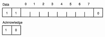
Each message is transmitted as a sequence of single byte communications, requiring only the presence of a single byte buffer in the receiving transputer to ensure that no information is lost. Each byte is transmitted as a start bit followed by a one bit followed by the eight data bits followed by a stop bit. After transmitting a data byte, the sender waits until an acknowledge is received; this consists of a start bit followed by a zero bit. The acknowledge signifies both that a process was able to receive the acknowledged byte, and that the receiving link is able to receive another byte. The sending link reschedules the sending process only after the acknowledge for the final byte of the message has been received.
Data bytes and acknowledges are multiplexed down each signal line. An acknowledge can be transmitted as soon as reception of a data byte starts (if there is room to buffer another one). Consequently transmission may be continuous, with no delays between data bytes.
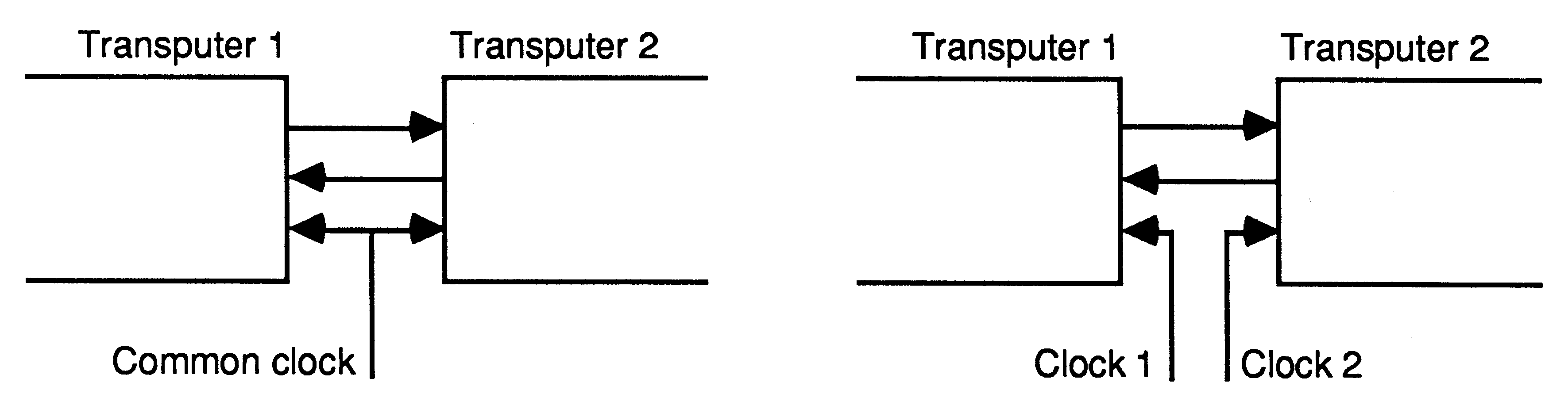
The links are designed to make the engineering of transputer systems straightforward. Board layout of two wire connections is easy to design and area efficient. All transputers will support a standard communications frequency of 10 Mbits/sec, regardless of processor performance. Thus transputers of different performance can be directly connected and future transputer systems will directly communicate with those of today.
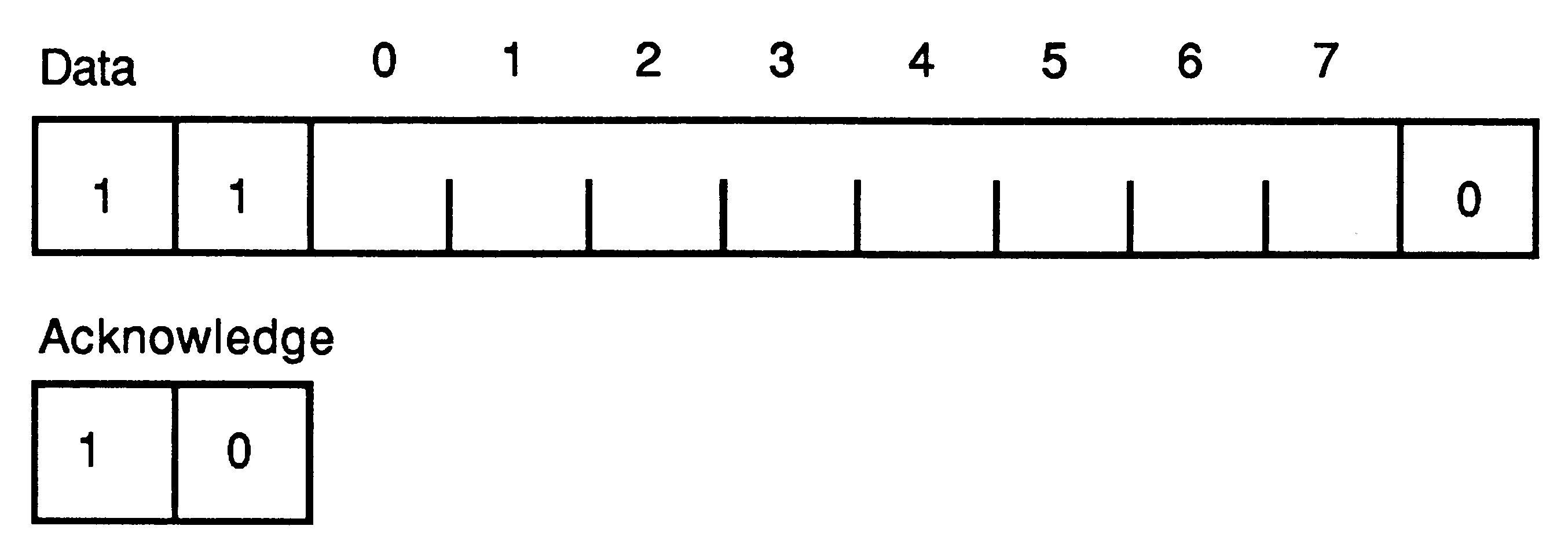
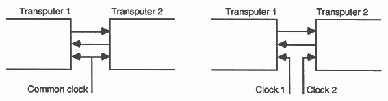
Link communication is not sensitive to clock phase. Thus, communication can be achieved between independently clocked systems as long as the communications frequency is the same.
The transputer family includes a number of link adaptor devices which provide a means of interfacing transputer links to non-transputer devices.
The purpose of this section is to describe how to access and control the resources of transputers using occam. A more detailed description is available in the occam programming manual and the transputer development system manual (provided with the development system).
The transputer development system will enable transputers to be programmed in other industry standard languages. Where it is required to exploit concurrency, but still to use standard languages, occam can be used as a harness to link modules written in the selected languages.
In occam, processes are connected to form concurrent systems. Each process can be regarded as a black box with internal state, which can communicate with other processes using point to point communication channels. Processes can be used to represent the behaviour of many things, for example, a logic gate, a microprocessor, a machine tool or an office.
The processes themselves are finite. Each process starts, performs a number of actions and then terminates. An action may be a set of sequential processes performed one after another, as in a conventional programming language, or a set of parallel processes to be performed at the same time as one another. Since a process is itself composed of processes, some of which may be executed in parallel, a process may contain any amount of internal concurrency, and this may change with time as processes start and terminate.
Ultimately, all processes are constructed from three primitive processes - assignment, input and output. An assignment computes the value of an expression and sets a variable to the value. Input and output are used for communicating between processes. A pair of concurrent processes communicate using a one way channel connecting the two processes. One process outputs a message to the channel and the other process inputs the message from the channel.
The key concept is that communication is synchronized and unbuffered. If a channel is used for input in one process, and output in another, communication takes place when both processes are ready. The value to be output is copied from the outputting process to the inputting process, and the inputting and outputting processes then proceed. Thus communication between processes is like the handshake method of communication used in hardware systems.
Since a process may have internal concurrency, it may have many input channels and output channels performing communication at the same time.
Every transputer implements the occam concepts of concurrency and communication. As a result, occam can be used to program an individual transputer or to program a network of transputers. When occam is used to program an individual transputer, the transputer shares its time between the concurrent processes and channel communication is implemented by moving data within the memory. When occam is used to program a network of transputers, each transputer executes the process allocated to it. Communication between occam processes on different transputers is implemented directly by transputer links. Thus the same occam program can be implemented on a variety of transputer configurations, with one configuration optimized for cost, another for performance, or another for an appropriate balance of cost and performance.
The transputer and occam were designed together. All transputers include special instructions and hardware to provide maximum performance and optimal implementations of the occam model of concurrency and communications.
All transputer instruction sets are designed to enable simple, direct and efficient compilation of occam. Programming of 110, interrupts and timing is standard on all transputers and conforms to the occam model.
Different transputer variants may have different instruction sets, depending on the desired balance of cost, performance, internal concurrency and special hardware. The occam level interface will, however, remain standard across all products.
After it starts execution, a process performs a number of actions, and then either stops or terminates. Each action may be an assignment, an input, or an output. An assignment changes the value of a variable, an input receives a value from a channel, and an output sends a value to a channel.
At any time between its start and termination, a process may be ready to communicate on one or more of its channels. Each channel provides a one way connection between two concurrent processes; one of the processes may only output to the channel, and the other may only input from it.
An assignment is indicated by the symbol :=. The example
v := e
|
sets the value of the variable v to the value of the expression e and then terminates. For example, x := 0 sets x to zero, and x := x + 1 increases the value of x by 1.
An input is indicated by the symbol ? The example
c ? x
|
inputs a value from the channel c, assigns it to the variable x and then terminates.
An output is indicated by the symbol ! The example
c ! e
|
outputs the value of the expression e to the channel c.
A number of processes can be combined to form a construct. A construct is itself a process and can therefore be used as a component of another construct. Each component process of a construct is written two spaces further from the left hand margin, to indicate that it is part of the construct. There are four classes of constructs namely the sequential, parallel, conditional and the alternative construct.
A sequential construct is represented by
SEQ
P1 P2 P3 ... |
The component processes P1, P2, P3 ... are executed one after another. Each component process starts after the previous one terminates and the construct terminates after the last component process terminates. For example
SEQ
c1 ? x x := x + 1 c2 ! x |
inputs a value, adds one to it, and then outputs the result.
Sequential constructs in occam are similar to programs written in conventional programming languages. Note, however, that they provide the performance and efficiency equivalent to that of an assembler for a conventional microprocessor.
A parallel construct is represented by
PAR
P1 P2 P3 ... |
The component processes P1, P2, P3 ... are executed together, and are called concurrent processes. The construct terminates after all of the component processes have terminated. For example,
PAR
c1 ? x c2 ! y |
allows the communications on channels c1 and c2 to take place together.
The parallel construct is unique to occam. It provides a straightforward way of writing programs which directly reflects the concurrency inherent in real systems. The implementation of parallelism on a single transputer is highly optimized so as to incur minimal process scheduling overhead.
Concurrent processes communicate only by using channels, and communication is synchronized. If a channel is used for input in one process, and output in another, communication takes place when both the inputting and the outputting processes are ready. The value to be output is copied from the outputting process to the inputting process, and the processes then proceed.
Communication between processes on a single transputer is via memory-to-memory data transfer. Between processes on different transputers it is via standard links. In either case the occam program is identical.
A conditional construct
IF
condition1 P1 condition2 P2 ... |
means that P1 is executed if condition1 is true, otherwise P2 is executed if condition2 is true, and so on. Only one of the processes is executed, and then the construct terminates. For example
IF
x = 0 y := y + 1 x <> 0 SKIP |
increases y only if the value of x is 0.
An alternative construct
ALT
input1 P1 input2 P2 input3 P3 ... |
waits until one of input1, input2, input3 ... is ready. If inputs first becomes ready, inputs is performed, and then process P1 is executed. Similarly, if input2 first becomes ready, input2 is performed, and then process P2 is executed. Only one of the inputs is performed, then its corresponding process is executed and then the construct terminates. For example:
ALT
count ? signal counter := counter + 1 total ? signal SEQ out ! counter counter := 0 |
either inputs a signal from the channel count, and increases the variable counter by 1, or alternatively inputs from the channel total, outputs the current value of the counter, then resets it to zero.
The ALT construct provides a formal language method of handling external and internal events that must be handled by assembly level interrupt programming in conventional microprocessors.
WHILE condition
P |
repeatedly executes the process P until the value of the condition is false. For example
WHILE (x - 5) > 0
x := x - 5 |
leaves x holding the value of (x remainder 5) if x were positive.
A replicator is used with a constructor to replicate the component process a number of times. For example, a replicator can be used with SEQ to provide a conventional loop.
SEQ i = 0 FOR n
P |
causes the process P to be executed n times.
A replicator may be used with PAR to construct an array of concurrent processes.
PAR i = 0 FOR n
P1 |
constructs an array of n similar processes P0, P1, ..., Pn-1. The index i takes the values 0, 1, ..., n-1, in P0, P1, ..., Pn-1 respectively.
Every variable, expression and value has a type, which may be a primitive type, array type, record type or variant type. The type defines the length and interpretation of data.
All implementations provide the types shown in table 1.
|
A declaration T x declares x as a new channel, variable, timer or array of type T. For example
INT x:
P |
declares x as an integer variable for use in process P.
Array types are constructed from component types. For example [ n ] T is an array type constructed from n components of type T.
A component of an array may be selected by subscription, for example v[e] selects the e’th component of v.
A set of components of an array may be selected by subscription, for example [v FROM e FOR c] selects the c components v[e], v[e + 1], ... v[e + c - 1]. A set of components of an array may be assigned, input or output.
A process may be given a name. For example
PROC square (INT n)
sqr := n * n : |
defines the procedure square. The name may be used as an instance of the process. For example
square (x)
|
is equivalent to
n IS x:
n := n * n |
An expression is constructed from the operators given in table 2, from variables, numbers, the truth values TRUE and FALSE, and the brackets ( and ).
|
For example, the expression
(5 + 7) / 2
|
evaluates to 6, and the expression
(#1DF /\ #FO) >> 4
|
evaluates to #D (the character # introduces a hexadecimal constant).
A string is represented as a sequence of ASCII characters, enclosed in double quotation marks ,. If the string has n characters, then it is an array of type [n]BYTE.
All transputers incorporate a timer. The implementation directly supports the occam model of time. Each process can have its own independent timer, which can be used for internal measurement or for real time scheduling.
A timer input sets a variable to a value of type INT representing the time. The value is derived from a clock, which changes at regular intervals. For example
tim ? V
|
sets the variable v to the current value of a free running clock, declared as the timer tim.
A delayed input takes the following form
tim ? AFTER e
|
A delayed input is unable to proceed until the value of the timer satisfies (timer AFTER e). The comparison performed is a modulo comparison. This provides the effect that, starting at any point in the timer’s cycle, the previous half cycle of the timer is considered as being before the current time, and the next half cycle is considered as being after the current time.
The implementation of occam provides for peripheral access by extending the input and output primitives with a port input/output mechanism. A port is used like an occam channel, but has the effect of transferring information to and from a block of addresses associated with a peripheral.
Ports behave like occam channels in that only one process may input from a port, and only one process may output to a port. Thus ports provide a secure method of accessing external memory mapped status registers etc.
Note that there is no synchronization mechanism associated with port input and output. Any timing constraints which result from the use of asynchronous external hardware will have to be programmed explicitly. For example, a value read by a port input may depend upon the time at which the input was executed, and inputting at an invalid time would produce unusable data.
During applications development it is recommended that the peripheral is modelled by an occam process connected via channels.
Occam programs may be configured for execution on one or many transputers. The transputer development system provides the necessary tools for correctly distributing a program configured for many transputers.
Configuration does not affect the logical behaviour of a program (see section four, Program development). However, it does enable the program to be arranged to ensure that performance requirements are met.
A parallel construct may be configured for a network of transputers by using the PLACED PAR construct. Each component process (termed a placement) is executed by a separate transputer. The variables and timers used in a placement must be declared within each placement process.
On any individual transputer, the outermost parallel construct may be configured to prioritize its components. Each process is executed at a separate priority. The first process has the highest priority, the last process has the lowest priority. Lower priority components may only proceed when all higher priority components are unable to proceed.
Each link provides one channel in each direction between two transputers.
A channel (which must already have been declared) is associated with a link by a channel association, for example:
PLACE Link0Input AT 4 :
|
Errors in occam programs are either detected by the compiler or can be handled at runtime in one of three ways.
The occam process STOP starts but never terminates. In method 1, an errant process stops and in particular cannot communicate erroneous data to other processes. Other processes will continue to execute until they become dependent on data from the stopped process. It is therefore possible, for example, to write a process which uses a timeout to warn of a stopped process, or to construct a redundant system in which several processes performing the same task are used to enable the system to continue after one of them has failed.
Method 1 is the preferred method of executing a program.
Method 2 is useful for program development and can be used to bring transputers to an immediate halt, preventing execution of further instructions. The transputer Error output can be used to inform the transputer development system that such an error has occurred. No variable local to the process can be overwritten with erroneous data, facilitating analysis of the program and data which gave rise to the error.
Method 3 is useful only for optimising programs which are known to be correct!
When a system has stopped or halted as a result of an error, the state of all transputers in the system can be analysed using the transputer development system.
For languages other than occam, the transputer provides facilities for handling individual errors by software.
The development of programs for multiple processor systems can involve experimentation. In some cases, the most effective configuration is not always clear until a substantial amount of work has been done. For this reason, it is desirable that most of the design and programming can be completed before hardware construction is started.
An important property of occam in this context is that it provides a clear notion of ’logical behaviour’; this relates to those aspects of a program not affected by real time effects.
It is guaranteed that the logical behaviour of a program is not altered by the way in which the processes are mapped onto processors, or by the speed of processing and communication. Consequently a program ultimately intended for a network of transputers can be compiled, executed and tested on a single computer used for program development.
Even if the application uses only a single transputer, the program can be designed as a set of concurrent processes which could run on a number of transputers. This design style follows the best traditions of structured programming; the processes operate completely independently on their own variables except where they explicitly interact, via channels. The set of concurrent processes can run on a single transputer or, for a higher performance product, the processes can be partitioned amongst a number of transputers.
It is necessary to ensure, on the development system, that the logical behaviour satisfies the application requirements. The only ways in which one execution of a program can differ from another in functional terms result from dependencies upon input data and the selection of components of an ALT. Thus a simple method of ensuring that the application can be distributed to achieve any desired performance is to design the program to behave ’correctly’ regardless of input data and ALT selection.
Performance information is useful to gauge overall throughput of an application, and has to be considered carefully in applications with real time constraints.
Prior to running in the target environment, an occam program should be relatively mature, and indeed should be correct except for, interactions which do not obey the occam synchronization rules. These are precisely the external interactions of the program where the world will not wait to communicate with an occam process which is not ready. Thus the set of interactions that need to be tested within the target environment are well identified.
Because, in occam, every program is a process, it is extremely easy to add monitor processes or simulation processes to represent parts of the real time environment, and then to simulate and monitor the anticipated real time interactions. The occam concept of time and its implementation in the transputer is important. Every process can have an independent timer enabling, for example, all the real time interactions to be modelled by separate processes and any time dependent features to be simulated.
A program portion which is separately compiled, and possibly written in a language other than occam, may be executed on a single transputer.
If the program is written in occam, then it takes the form of a single PRoc, with only channel parameters. If the program is written in a language other than occam, then a run-time system is provided which provides input/output to occam channels.
Such separately compiled program portions are linked together by a framework of channels, termed a harness. The harness is written in occam. It includes all configuration information, and in particular specifies the transputer configuration in which the separately compiled program portion is executed.
Transputers are designed to allow efficient implementations of high level languages, such as C, Pascal and Fortran. Such languages will be available in addition to occam.
At runtime, a program written in such a language is treated as a single occam process. Facilities are provided in the implementations of these languages to allow such a program to communicate on ’occam’ channels. It can thus communicate with other such programs, or with programs written in occam. These programs may reside on the same transputer, in which case the channels are implemented in store, or may reside on different transputers, in which case the channels are implemented by transputer links.
It is therefore possible to implement ’occam’ processes in conventional high level languages, and arrange for them to communicate. It is possible for different parts of the same application to be implemented in different high level languages.
The standard input and output facilities provided within these languages are implemented by a well-defined protocol of communications on ’occam’ channels.
The development system provides facilities for management of separately compiled occam.
The low level memory model is of a signed address space.
Memory is byte addressed, the lowest addressed byte occupying the least significant byte position within the word.
The implementation of occam supports the allocation of the code and data areas of an occam process to specific areas of memory. Such a process must be a separately compiled PROC, and must not reference any variables and timers other than those declared within it.
All transputers have several links. The link protocol and electrical characteristics form a standard for all INMOS transputer and peripheral products.
All transputers support a standard link communications frequency of 10 megabits per second. Some devices also support other data rates. Maintaining a standard communications frequency means that devices of mixed performance and type can intercommunicate easily.
Each link consists of two unidirectional signal wires carrying both data and control bits. The link signals are TTL compatible so that their range can be easily extended by inserting buffers.
The INMOS communication links provide for communication between devices on the same printed circuit board or between printed circuit boards via a back plane. They are intended to be used in electrically quiet environments in the same way as logic signals between TTL gates.
The number of links, and any communication speeds in addition to the standard speed of 10 Mbits/sec, are given in the product data for each product.
The quiescent state of the link signals is low, for a zero. The link input signals and output signals are standard TTL compatible signals.
For correct functioning of the links the specifications for maximum variation in clock frequency between two transputers joined by a link and maximum capacitive load must be met. Each transputer product also has specified the maximum permissible variation in delay in buffering, and minimum permissible edge gradients. Details of these specifications are provided in the product data.
Provided that these specifications are met then any buffering employed may introduce an arbitrary delay into a link signal without affecting its correct operation.
At all times the specification of input voltages with respect to the GND and VCC pins must be met. This includes the times when the VCC pins are ramping to 5 V, and also while they are ramping from 5 V down to 0 V.
The system services comprise the clocks, power, and signals used for initialization.
The specification includes minimum times that VCC must be within specification, the input clock must be oscillating, and the Reset signal must be high before Reset goes low. These specifications ensure that internal clocks and logic have settled before the transputer starts.
When the transputer is reset the memory interface is initialised (if present and configurable).
The processor and INMOS serial links start after reset. The transputer obeys a bootstrap program which can either be in off-chip ROM or can be received from one of the links. How to specify where the bootstrap program is taken from depends upon the type of transputer being used. The program will normally load up a larger program either from ROM or from a peripheral such as a disk.
During power down, as during power up, the input and output pins must remain within specification with respect to both GND and VCC.
A software error, such as arithmetic overflow, array bounds violation or divide by zero, causes an error flag to be set in the transputer processor. The flag is directly connected to the Error pin. Both the flag and the pin can be ignored, or the transputer stopped. Stopping the transputer on an error means that the error cannot cause further corruption.
As well as containing the error in this way it is possible to determine the state of the transputer and its memory at the time the error occurred.
All transputers operate from a standard 5MHz input clock. High speed clocks are derived internally from the low frequency input to avoid the problems of distributing high frequency clocks. Within limits the mark-tospace ratio, the voltage levels and the transition times are immaterial. The limits on these are given in the product data for each product. The asynchronous data reception of the links means that differences in the clock phase between chips is unimportant.
The important characteristic of the transputer’s input clock is its stability, such as is provided by a crystal oscillator. An R-C oscillator is inadequate. The edges of the clock should be monotonic (without kinks), and should not undershoot below -0.5 V.
The program which is executed after reset can either reside in ROM in the transputer’s address space or it can be loaded via any one of the transputer’s INMOS serial links.
The transputer bootstraps from ROM by transferring control to the top two bytes in memory, which will invariably contain a backward jump into ROM.
If bootstrapping from a link, the transputer bootstraps from the first link to receive a message. The first byte of the message is the count of the number of bytes of program which follow. The program is loaded into memory starting at a product dependent location MemStart, and then control is transferred to this address.
Messages subsequently arriving on other links are not acknowledged until the transputer processor obeys a process which inputs from them. The loading of a network of transputers is controlled by the transputer development system, which ensures that the first message each transputer receives is the bootstrap program.
All transputers contain one or more INMOS serial links. Certain transputer products also have other applicationspecific interfaces. The peripheral control transputers contain specialized interfaces to control a specific peripheral or peripheral family.
In general, a transputer based application will comprise a number of transputers which communicate using INMOS links. There are three methods of communicating with peripherals.
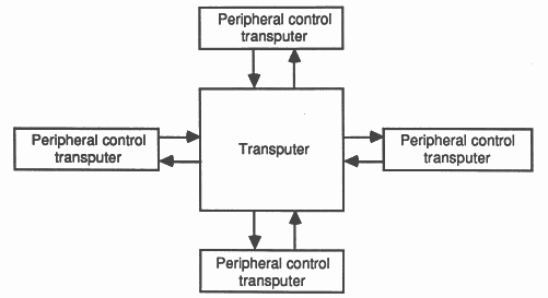
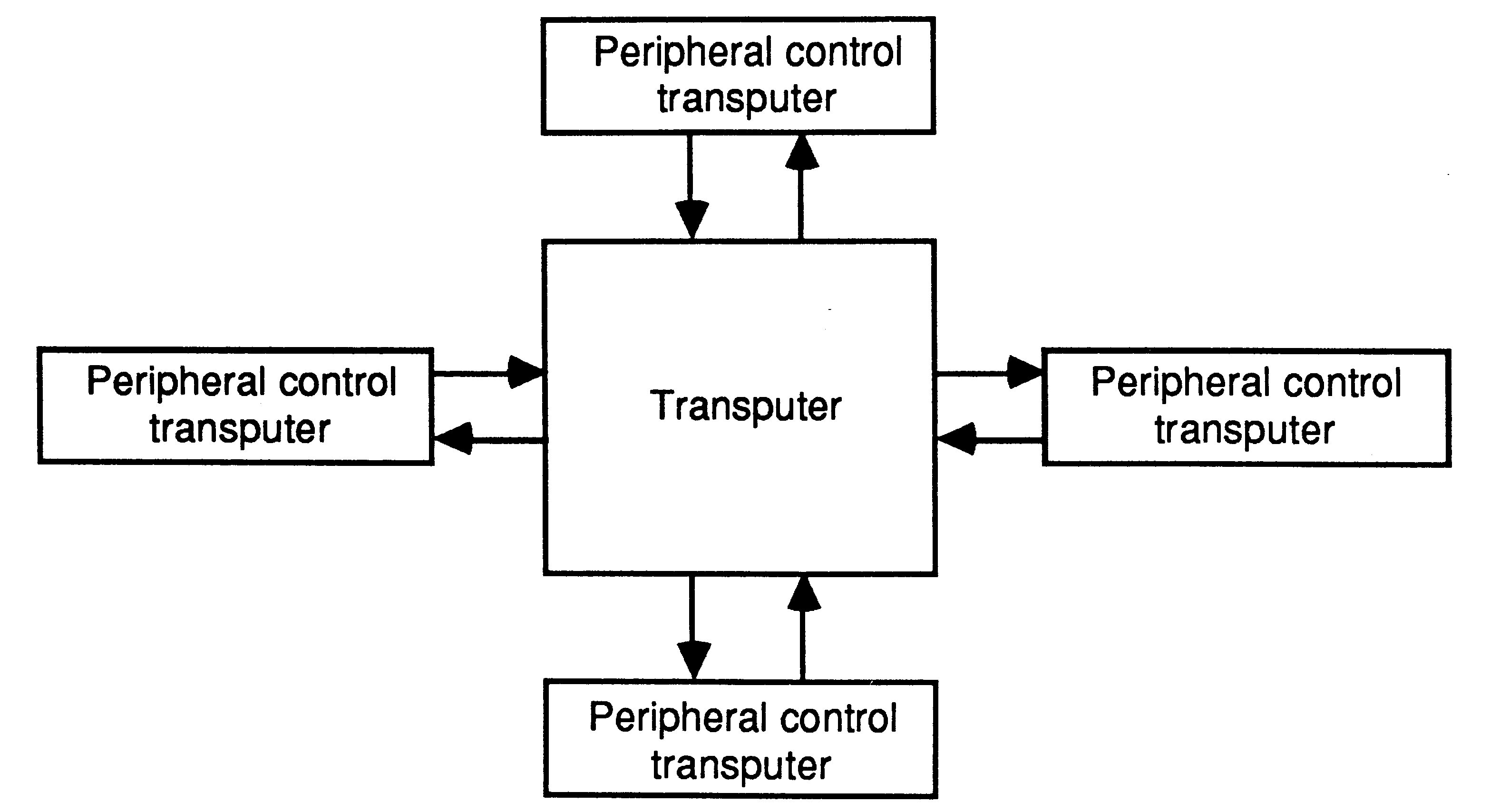
The first is by employing peripheral control transputers (eg for graphics or disks), in which the transputer chip connects directly to the peripheral concerned (figure 8). The interface to the peripheral is implemented by special purpose hardware within the transputer. The application software in the transputer is implemented as an occam process, and controls the interface via occam channels linking the processor to the special purpose hardware.
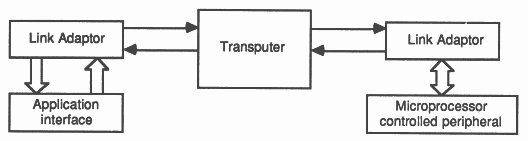
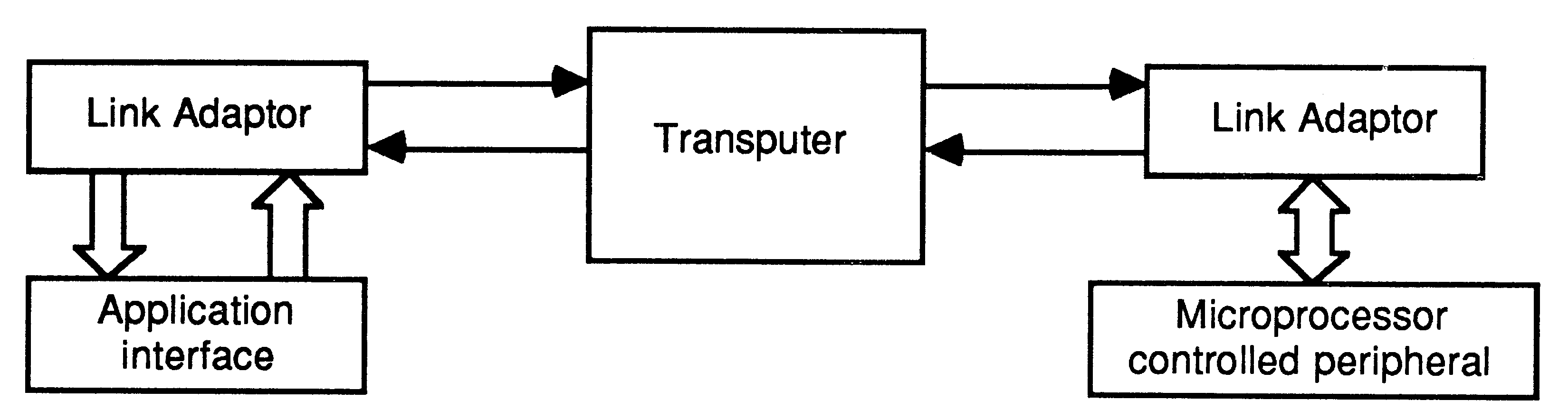
The second method is by employing link adaptors (figure 9). These devices convert between a link and a specialized interface. The link adaptor is connected to the link of an appropriate transputer, which contains the application designer’s peripheral device handler implemented as an occam process.
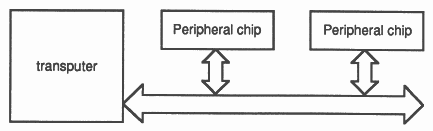
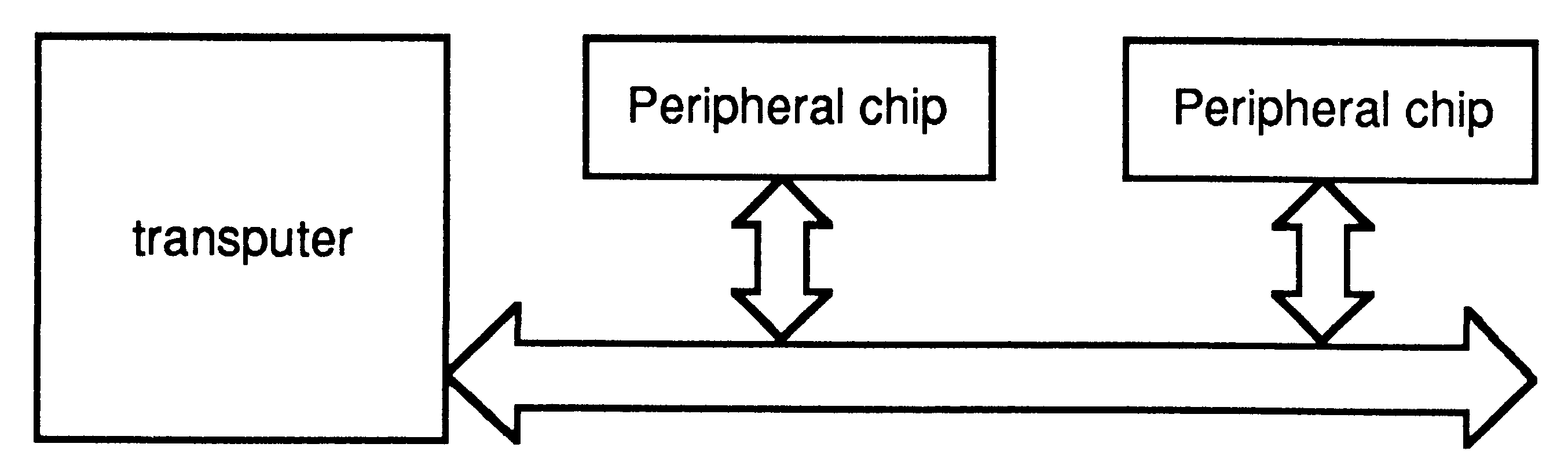
The third method is by memory mapping the peripheral onto the memory bus of a transputer (figure 10). The peripheral is controlled by memory accesses issued as a result of PORT inputs and outputs. The application designer’s peripheral device handler provides a standard occam channel interface to the rest of the application.
The first transputers implement an event pin which provides a simple means for an external peripheral to request attention from a transputer.
In all three methods, the peripheral driver interfaces to the rest of the application via occam channels. Consequently, a peripheral device can be simulated by an occam process. This enables testing of all aspects of a transputer system before the construction of hardware.
The bits in a byte are numbered 0 to 7, with bit 0 the least significant. The bytes in words are numbered from 0, with byte 0 least significant. In general, wherever a value is treated as a number of component values, the components are numbered in order of increasing numerical significance, with the least significant component numbered 0. Where values are stored in memory, the least significant component value is stored at the lowest (most negative) address. Similarly, components of arrays are numbered starting from 0, and stored in memory with component 0 at the lowest address.
Where a byte is transmitted serially, it is always transmitted least significant bit (0) first. In general, wherever a value is transmitted as a number of component values, the least significant component is transmitted first. Where an array is transmitted serially, component 0 is transmitted first. Consequently, block transfers to and from memory are performed starting with the lowest (most negative) address and ending with the highest (most positive) one.
In diagrams, the least significant component of a value is to the right hand side of the diagram, component 0 of an array is at the bottom of the diagram and memory locations with more negative addresses are also to the bottom of the diagram.
The signal names, identifying the individual pins on a transputer chip, have been chosen to avoid being cryptic, giving as much information as possible.
All transputer signals described in the text of this manual are printed in bold.
The majority of transputer signals are active high. Those which are active low have names commencing with not.
All INMOS products - both memories and transputers - have a number of the form
IMS xxxx-xx
|
The main field identifies the product, and the field after the hyphen is used for speed variants, etc. Extra letters are sometimes introduced, eg for military quality products.
The initial character of the main field is a digit for memory products, a letter for transputer products. The particular letter indicates the type of transputer product (table 3). Support products are numbered as shown in table 4.
|