|
|
| Transputer Instruction Set _____________________________________________________________________ |
| Guy Harriman November 29, 1988 |
Two instructions exist in the transputer instruction set which are additional to the instruction set published in the ”Compiler Writer’s Guide”, and which are useful to those writing loaders and debuggers.
The two instructions concerned are start, and testhardchan. The instructions are described and defined in this document.
The other set of instructions documented here are to allow testing of the internal CPU registers which are not normally visible to the user.
These instructions are present on all the current transputer family members, that is on the IMS T212, IMS T222, IMS T414, IMS T425, IMS T800, IMS T801, and IMS M212, and on all compatible future transputers.
The instructions may be accessed using ASM statements in C, and using the GUY construct in the D700D transputer development system occam compiler. The occam compiler recognises testhardchan, and some of the register test instructions. However, it generates incorrect code for start. The instructions can be accessed by using pfix and opr, for example, start (opcode #1FF) can be coded as pfix 1, pfix F, opr F, (#21 2F FF). See ”The Transputer Instruction Set: A Compiler Writer’s Guide” published by Prentice Hall (ISBN 0-13-929100-8) for more information.
The purpose of the start instruction is to start the transputer processor after a Reset or an Analyse has been performed.
The opcode for the start instruction is loaded directly into the CPU microcode rom by the Reset pin being taken high; therefore the first microword of the start instruction is repeated all the time that the Reset pin is held high. Furthermore, if an Analyse has been performed by taking the Analyse pin high before taking the Reset pin high, then the first microword of the start instruction is repeated until the Analyse pin has been taken low, after the Reset pin has been taken low.
The Reset pin also has the function of resetting the control logic of the Links. The Links are capable of receiving data after the Reset pin has been taken low, whether a Reset or an Analyse has been performed.
The Reset pin forces the configurable external memory interface of the IMS T414, IMS T425, and IMS T800 to reconfigure, if the transputer is not performing an Analyse.
The start instruction may be executed to cause the transputer to go into the booting state. However, the other effects of Reset cannot be caused without taking the Reset pin high.
The start instruction has the following function:
The timer alarms are switched off for both low and high priority, preventing any process on the timer queue from making an interrupt to the processor. The timeslice logic is cleared, to allow the first process a full timeslice period.
If BootFromRom is high, then the code placed at the most significant two bytes in memory (at address MaxInt - 2) is jumped to. Typically this code consists of nfix j, allowing a jump of -256 bytes. A small negative jump may be used to a second jump instruction to anywhere in memory.
If BootFromRom is low, then the first Link to receive a byte is used to provide the boot code or the protocol to perform a memory access (’peeking’ to read, ‘poking’ to write).
If the value of the first byte sent to a Link is greater than one, then that number of bytes is inputted through the same Link to MemStart and above, and MemStart then jumped to. This permits bootstrapping to be performed.
The memory access protocol has the following form. If the first byte sent is zero, then a word of address is inputted, followed by a word of data which is written to that address. If the first byte sent is one, then a word of address is inputted, then the word of data which is read from that address is outputted. The value held at MemStart (the location used for inputting the first byte and the address for a Link memory access) is saved by the processor, and restored before the read from the Link is enabled. The count value of the booting input channel is preserved during start, and placed back into the stack of the Link input channel.
Any Link can be used for peeking and poking. As long as the full peek and poke protocols are followed down a single Link, then any number of sequential peeks and pokes down any links may be performed before bootstrapping takes place. As soon as a protocol byte is sent to a transputer which is waiting to be bootstrapped down a Link, which is not zero or one in value, then the Link bootstrap must be completed down that Link. It is not possible to peek or poke down a Link after bootstrapping has started.
The start instruction performs a poll of the Link inputs, finding if a byte has arrived at each Link in turn. The first Link tried is Link 0, followed by Link 1, then Link 2, then Link 3, and returning to Link 0. If a byte has been received at a Link, then the value of the byte is examined by the processor to determine the action to be taken. Only when a peek or a poke is requested will the polling of the Links be continued, allowing any number of peeks and pokes to be performed down any of the Links before bootstrapping.
The Reset pin causes the two instruction buffer registers to be set Full, thus avoiding any code fetches during the execution of the start instruction, before the jump to the bootstrap code at the end of the start instruction.
The purpose of the testhardchan instruction is to allow the Link registers to be tested. The instruction is useful for debugging as well as manufacturing test, as it allows a post-mortem debugger to determine the state of all the message transfers occurring on the system at the time of analysis.
The testhardchan instruction will only work when no Links are active, because the processor has to take control of the Ubus for passing data from the channel stack to the processor. The Links otherwise always have control of the Ubus. The purpose of the Ubus is to allow data to be transfered between the Links and memory.
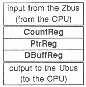
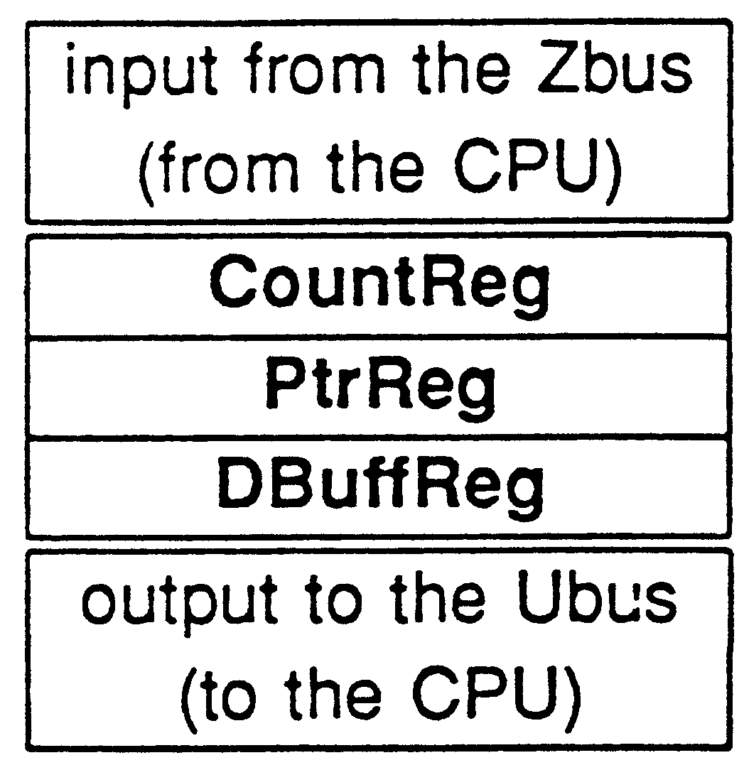
Each channel stack is a pushdown-only stack of three registers, CountReg, PtrReg, and DBuffReg. A value can be pushed from the CPU onto the channel stack, with the DBuffReg value being pushed out of the channel stack. The channel stack registers are in the following order:
|
|
The testhardchan instruction pushes the BReg data into the stack of the channel identified by AReg, and saves the DBuffReg at the bottom of the channel stack in AReg. This instruction is not valid if any transfers are occurring while it is executed, as it assumes use of the Ubus.
Therefore to obtain all the values of the registers in Link 0 input channel, and clear the registers to zero, for example, the following code sequence could be used:
LDC 0 -- data for DBuffReg MINT LDNLP 4 -- address of Link 0 input word TESTHARDCHAN STL dbuffvalue -- save original DBuffReg contents LDC 0 -- data for PtrReg MINT LDNLP 4 -- address of Link 0 input word TESTHARDCHAN STL ptrvalue -- save original PtrReg contents LDC 0 -- data for CountReg MINT LDNLP 4 -- address of Link 0 input word TESTHARDCHAN STL countvalue -- save original CountReg contents |
The value in the CountReg after an analyse has been performed is particularly interesting. If a message is in progress, then the CountReg holds [MINUS (number of bytes still to send or receive)]. If the channel is not enabled to transfer data, that is the Link input or output word contains NotProcess.p (= MinInt), then the CountReg contains zero. However, an input channel will contain a value of one in the CountReg if the corresponding output channel connected to it has sent an unsolicited byte. An unsolicited byte is the byte sent by an output channel which has been enabled to send a message before the connected input channel has been enabled to receive that message. This is the case of an input channel being ready for an alternative (ALT). The output channel CountReg is incremented on each acknowledge received. The input channel CountReg is incremented on each data byte received.
The PtrReg is a word address register which points to the next word in memory to be written to or read from by the channel. Link data is always read as words. At the beginning and end of messages, only the bytes required within a word are written. These bytes are written by selecting the required byte write enables in the memory write access. Therefore the minimum number of word (and partial word) memory accesses are made to perform a Link transfer.
The DBuffReg holds data to be written to memory for input channels, or the data which has been read from memory for the output channels. The DBuffReg is connected to a shift register, which inputs or outputs serial data through the Link pins. The shift register operates in parallel with the loading from memory, or storing to memory of the DBuffReg, in order to achieve the double-buffering of Link data. The purpose of the double-buffering of Link data is to maintain a continuous transfer rate, independent of memory accesses in the CPU.
None of these registers are affected by Reset or Analyse, apart from the boot input channel when using boot from Links, and the output channel of the Link if a Link peek is performed. The count value of the booting input channel is preserved during the bootstrap from Link procedure, and placed back into the CountReg of the Link input channel when the bootstrap message has been received.
Two registers (DReg and EReg) outside the CPU stack are provided in the datapath for use by the microcode, as part of the requirement for the process scheduling operations.
The StatusReg holds the error flag of the processor, and contains bits which are used by the microcode to restart interrupted instructions (block move, soft channel output, adding or removing processes from the timer queues), and bits which control modes of operation (breakpoint enable, halt on error, and the two dimensional block move and transparency for the graphics on the IMS T800).
The DReg, EReg, and StatusReg are not saved along with the stack on interrupt by the Links and timer alarms. The DReg is never saved on interrupt. The EReg is saved on interrupt only when the in or out instruction is executed on a soft channel at low priority and the corresponding outputting or inputting process is ready (has already executed the out or in instruction on that channel). The StatusReg is saved on interrupt only when it carries information about the type of instruction which was being executed at the time of interrupt, but is not saved if the interrupt happened between instructions. The interruptable instructions are move, tin, taltwt, and disc.
The testing of DReg, EReg, and StatusReg is performed by using instructions which access them from the stack; these instructions are not part of the main instruction set. Three instructions push the value of the register to be tested onto the CPU stack. The other three instructions pop the value of top of the CPU stack into the register to be tested.
These test instructions are present on all transputers; the opcodes used are the same on all transputers.
| Operation | Memory | Mnemonic | Processor | Name |
| Code | Code | Cycles | ||
| 1FF | 21 2F FF | start | - | start processor |
| Operation | Memory | Mnemonic | Processor | Name |
| Code | Code | Cycles | ||
| 2D | 22 FD | testhardchan | 3 | test hard channel stack |
| 25 | 22 F5 | testldd | 1 | load D register |
| 28 | 22 F8 | teststd | 1 | store D register |
| 24 | 22 F4 | testlde | 1 | load E register |
| 27 | 22 F7 | testste | 1 | store E register |
| 23 | 22 F3 | testlds | 1 | load status register |
| 26 | 22 F6 | teststs | 1 | store status register |
In the following specifications:
| start #1FF | start processor |
| IF
| |
| BootFromRom
| |
| SEQ
| |
| Areg := Iptr
| |
| Breg := Wdesc
| |
| Iptr := ResetCodePtr -- = MaxInt - 2
| |
| Wptr := MemStart
| |
| ProcPriority := 1 -- low priority
| |
| STATUSreg := STATUSreg AND PreservedBits
| |
| NOT BootFromRom
| |
| SEQ
| |
| PollLinkInputs(FirstByte)
| |
| WHILE (FirstByte < 2)
| |
| IF
| |
| FirstByte = 0
| |
| SEQ
| |
| -- Perform Link Memory Write (Poke)
| |
| InputAddressFromSelectedLink
| |
| InputDataFromSelectedLink
| |
| Memory[Address] := Data
| |
| PollLinkInputs(FirstByte)
| |
| FirstByte = 1
| |
| SEQ
| |
| -- Perform Link Memory Read (Peek)
| |
| InputAddressFromSelectedLink
| |
| Data := Memory[Address]
| |
| OutputDataToSelectedLink
| |
| PollLinkInputs(FirstByte)
| |
| InputBootCodeFromSelectedLink(FirstByte,MemStart)
| |
| Areg := Iptr
| |
| Breg := Wdesc
| |
| Creg := Identity of Bootstrap Link
| |
| Iptr := MemStart
| |
| Wptr := First Free Word
| |
| ProcPriority := 1 -- low priority
| |
| STATUSreg := STATUSreg AND PreservedBits
| |
| testhardchan #2D | test hard channel stack |
| SelectedChannel := AReg
| |
| AReg := DBuffReg
| |
| DBuffReg := PtrReg
| |
| PtrReg := CountReg
| |
| CountReg := BReg
| |
| BReg := CReg
| |
| Iptr := NextInst
| |
| testldd #25 | load D register |
| CReg := BReg
| |
| BReg := AReg
| |
| AReg := DReg
| |
| Iptr := NextInst
| |
| teststd #28 | store D register |
| DReg := AReg
| |
| AReg := BReg
| |
| BReg := CReg
| |
| Iptr := NextInst
| |
| testlde #24 | load E register |
| CReg := BReg
| |
| BReg := AReg
| |
| AReg := EReg
| |
| Iptr := NextInst
| |
| testste #27 | store E register |
| EReg := AReg
| |
| AReg := BReg
| |
| BReg := CReg
| |
| Iptr := NextInst
| |
| testlds #23 | load status register |
| CReg := BReg
| |
| BReg := AReg
| |
| AReg := StatusReg
| |
| Iptr := NextInst
| |
| teststs #26 | store status register |
| StatusReg := AReg
| |
| AReg := BReg
| |
| BReg := CReg
| |
| Iptr := NextInst
| |