|
|
| Extraordinary use of
transputer links
_____________________________________________________________________ |
| INMOS 72-TCH-001 |
The transputer link architecture provides ease of use and compatibility across the range of transputer products. The transputer link is asynchronous at the bit level, which removes the need to distribute a clock within tight phase constraints; indeed, separate clocks can be used to supply the transputers within a system. The use of a handshake protocol at the byte level allows fast systems to communicate with slow systems without overrun problems. Finally, the provision of synchronised communication at the message level matches the occam model of communication.
Transputer links are intended to be used for communication within a system of devices connected on the same PCB or via a backplane. The links are TTL compatible. This allows the use of simple buffers and determines their DC noise margins. If transputer links are used within their specifications (Vcc, clock fitter, clock frequency, data skew, and decoupling) they are extremely reliable; there will no run out errors on clocking and the synchronisation failure rate has been designed to be less than 1 failure per 1025 samples.
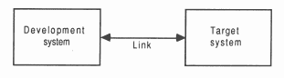
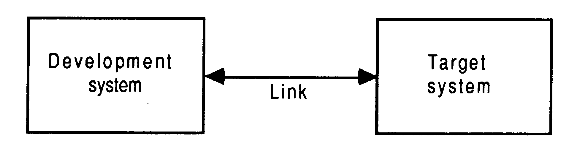
In certain circumstances, such as communication between a development system and a target system, or for communication via an unreliable interconnect, it is desirable to use a transputer link even though the synchronised message passing of occam is not exactly what is required. Such extraordinary use of transputer links is possible but requires careful programming and the use of some special pre-defined occam procedures. This note explains how to use these procedures and gives two examples of their use.
It is essential to have a clear idea of the requirements of a system in order to program extraordinary use of the transputer links. We have two cases to consider here. The first is of a system consisting of two distinct parts connected via a link. Here the requirement is to insulate each system from the other, perhaps allowing one system to monitor to behaviour of the other. The second case is of a system which uses an unreliable interconnect, where there is a danger of disconnection, or if the link is used outside its specified noise margins, a danger of data corruption.
As an example, consider a development system connected via a link to a target system. The development system compiles and loads programs onto the target and also provides the program executing in the target with access to facilities such as a file store. Suppose the target halts (due to a bug) whilst it is engaged in communication with the development system. The development system then has to analyse the target system.
A problem will arise if the development system is written in ’pure’ occam. It is possible that when the target system halts, the development system is in the middle of communicating. As a result, the input or output process will not terminate and the development system will be unable to continue. This problem can occur even where an input occurs in an alternative construct together with a timeout (as illustrated below). When the first byte of a message is received the process performing the alternative commits to inputting; the timer guard cannot subsequently be selected. Hence, if insufficient data is transmitted the input will not terminate.
ALT
TIME ? AFTER timeout ... from.other.system ? message ... |
It is important to note that the problem arises from the need to recover from the communication failure. It is perfectly straightforward to detect the failure within ’pure’ occam, and this is quite sufficient for implementing resilient systems with multiple redundancy.
In the case of communication via an unreliable interconnect there are a number of possible failure modes; If the interconnect becomes disconnected whilst a data transfer is in progress the communication will not complete. It is possible that this might manifest itself to only one of the systems; if the disconnection occurs after all the data packets have been transmitted but before the final acknowledge packet has been transmitted then the inputting system will see a completed transfer but the outputting system will hang. It is also possible for a disconnection to cause data corruption or the conversion of a data packet into an acknowledge packs (see next paragraph).
If a link is being used outside its noise margins there are a number of errors which may occur. The first is the corruption of the content of a data packet which will lead to the reception of erroneous data. This may be detected by the use of standard checking techniques such as checksums or CRCs. Otherwise, an error will involve the generation of, the deletion of, or the corruption of a packet. This will lead to the breakdown of the end-to-end synchronisation of the protocol, and ultimately, will cause one, or both, of the communicating processes to hang on a communication.
For example, if a data packet is lost, it will not be acknowledged by the receiving transputer. Hence, the transmitting transputer will neither be able to transmit any further data packets, nor to schedule the outputting process. Consequently, the receiving transputer will never receive sufficient data packets to schedule the inputting process. Hence neither the inputting process, nor the outputting process will terminate.
The first concern of a designer is to understand how to recognise the occurrence of a failure. This will depend on the system; for example, in some cases a timeout may be appropriate.
The second concern is to use ensure that even if a communication fails, all input processes and output processes will terminate. As this cannot be achieved directly in occam, INMOS provides a number of predefined procedures which perform the required function. These are described below.
The final concern is to be able to recover from the failure and to re-establish communication on the link. This involves reinitialising the link hardware; again INMOS provides a suitable pre-defined procedure to allow this to be performed.
There are four predefined procedures which implement input and output processes which can be made to terminate even when there is a communication failure. They will terminate either as the result of the communication completing, or as the result of the failure of the communication being recognised. Two procedures provide input and output where communication failure can be detected by a simple timeout, the other two procedures provide input and output where the failure of the communication is signalled to the procedure via a channel. The procedures have a boolean variable as a parameter which is set true if the procedure terminated as a result of communication failure being detected, and is set false otherwise. If the procedure does terminate as a result of communication failure having been detected then the link channel will be reset (see later).
All four predefined procedures take as parameters a link channel c (on which the communication is to take place), a byte vector mess (which is the object of the communication) and the boolean variable aborted. The choice of a byte vector as the parameter to these procedures allows an object of any type to be passed along the channel provided it is retyped first.
The two procedures for communication where failure is detected by a timeout take a timer parameter TIME, and an absolute time t. The procedures treat the communication as having failed when the time as measured by the timer TIME is AFTER the specified time t. The names and the parameters of the procedures are:
InputOrFail.t(CHAN c, []BYTE mess, TIMER TIME, INT t, BOOL aborted)
|
and
OutputOrFail.t(CHAN c, VAL []BYTE mess, TIMER TIME, INT t, BOOL aborted)
|
The other two procedures provide communication where failure cannot be detected by a simple timeout. In this case failure must be signalled to the inputting or outputting procedure via a message on the channel kill. The message is of type INT. The names and parameters to the procedures are:
InputOrFail.c(CHAN c, []BYTE mess, CHAN kill, BOOL aborted)
|
and
OutputOrFail.c(CHAN c, VAL []BYTE mess, CHAN kill, BOOL aborted)
|
To reuse a link after a communication failure has occurred it is necessary to reinitialise the link hardware. This involves reinitialising both ends of both channels implemented by the link. Furthermore, the reinitialisation must be done after all processes have stopped trying to communicate on the link. So, although the InputOrFail and OutputOrFail procedures do, themselves, reset the link channel when they abort a transfer, it is necessary to use the fifth pre-defined procedure Reinitialise(CHAN c), after it is known that all activity on the link has ceased.
The Reinitialise pre-defined must only be used to reinitialise a link channel after communication has finished. If the procedure is applied to a link channel which is being used for communication the transputer’s error flag will be set and subsequent behaviour is undefined.
The following examples illustrate two systems which make extraordinary use of transputer links. The first example is a development system, the second example is of two systems interconnected by a link which may be physically disconnected and re-connected at any time.
The problem
For our example we return to the development system described above.
|
|
The solution
The first step in the solution is to recognise that the development system knows when a failure might occur and hence the development system knows when it might be necessary to abort a communication.
We will assume that the process which interfaces to the target system is sent a message when the development system decides to reset the target causing the interface process to abort any transfers in progress. The development system can then reset the target system (which resets the target end of the link) and re-initialise the link.
We can now outline the construction of such a system. The program below would be that part of the development system which runs once the target system starts executing, until such time as the target is reset and the link is reinitialised.
SEQ
CHAN terminate.input, terminate.output : PAR ... interface process ... monitor process ... reset target system Reinitialise(link.in) Reinitialise(link.out) |
The monitor process will output on both terminate.input and terminate.output when it detects an error in the target system.
The interface process consists of two processes running in parallel, one which outputs to the link, the other which inputs from the link. As the structure of the processes is similar we only discuss the process which outputs to the link. If there were no need to consider the possibility of communication failure the process might be
WHILE active
SEQ ... ALT terminate.out ? any active := FALSE from.dev.system ? message link.out ! message ... |
This process will loop, forwarding input from from.dev.system to link.out, until it receives a message on terminate.out. However, if after this process has attempted to forward a message, the target system halts without inputting, the interface process will fail to terminate.
The following program overcomes this problem:
WHILE active
BOOL aborted : SEQ ... ALT terminate.out ? any active := FALSE from.dev.system ? word SEQ OutputOrFail.c(link.out, message, terminate.out, aborted) active := NOT aborted |
This program is always prepared to input from terminate.out, and is always terminated by an input from terminate.out. There are two cases which can occur. The first is that the message is received by the input which then sets active to false. The second is that the output gets aborted. In this case the whole process is terminated because the variable aborted would then be true.
The problem
In this example we consider two transputer-based systems, connected by a link. The particular problem with which we are concerned is that the link between the two systems might become disconnected. (We assume that the electrical design of the system is adequate).
This example illustrates two things. Firstly how to detect that the link has become disconnected, and secondly how to restart communication after it is re-connected.
The solution
The key to this solution is detecting the disconnection of the link. Unlike the development system example we do not straightforwardly know when this has occurred. For example, if one system has not received communication from the other system for thirty minutes it cannot necessarily deduce that the link has been disconnected; it may just be that the other system has not tried to communicate for thirty minutes!
To overcome this problem we adopt the use of ’watchdog’ processes on each system to ensure that it communicates frequently with the other system. The frequency of communication is chosen so that the disconnection of the link is detected as quickly as is required by a system.
In this solution each system contains a process which interfaces to the communication link. This process connects to an input channel, an output channel and both the channels implemented by the link. The outline of this process is as follows:
TIMER TIME :
PROC copier(CHAN output, input, unreliable.in, unreliable.out) INT start.time : SEQ ... synchronise with other end TIME ? start.time WHILE active SEQ ... copy until failure occurs ... resynchronise |
For simplicity we will assume that the system starts with the link connected. First, the two systems synchronise by passing a message. This establishes a common timeframe for the two systems (used when we need to re-establish communication after disconnection of the link). Then the systems copy information between themselves until the link is disconnected. If one system detects a failure it ensures that the other system detects a failure by deliberately not engaging in communication for a suitable period. The two systems then attempt to re-establish communication.
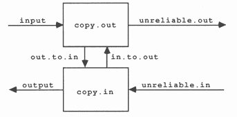
The copier performs the copying using two processes running in parallel, as follows:
CHAN in.to.out, out.to.in :
PAR copy.in (unreliable.in, output, out.to.in, in.to.out, one.sec) copy.out (unreliable.out, input, in.to.out, out.to.in, one.sec/4) |
|
|
The channels in.to.out and out.to.in enable each process to signal the other when one detects failure. The processes implement a protocol on the link channels with two types of packet, ’data’ and ’tick’ packets. A data packet is a ’data’ tag, followed by a message, a tick packet consists of just a ’tick’ tag. In this example both the tag and the message are one word long.
The processes forward and receive messages as needed and insert tick packets if there are no message being forwarded. The disconnection of the link is detected either by the input process or the output process failing to communicate within their allotted time.
In this example the outputting process outputs at least once every quarter second (on unreliable.out) and assumes that the link has been disconnected if the output does not complete within a quarter second. The inputting process will assume the link has become disconnected if it does not receive a message (on unreliable.in) for one second.
The coding of the two procedures copy.in and copy.out can now be explained. The program text is given in section 7. Both procedures (A) declare an integer mess and then retype it to a byte array mess.a. This allows the integer mess to be passed to the predefined procedures which require a byte array as a parameter. The main loop of both procedures (B) continue until either the procedure receives a message which tells it that the other procedure, running in parallel, has detected link disconnection (C), or it has detected an error itself (G).
The other possibilities for the main loop of copy.out are to receive a message on channel output (E) or to determine that it is time to send a ’tick’ (D). In both cases an OutputOrFail.t is used in case die link is disconnected whilst copy.out is outputting.
If copy.in does not receive a message on error.det it will perform an input (F). This is done using InputOrFail.t which will detect link disconnection if the timeout is exceeded.
Each process contains program to inform the other, parallel, process when it detects an error (G). This runs an input in parallel with an output to ensure that if the other parallel process has performed an output, the communication will occur correctly. Correspondingly, if the procedure is informed that an error has occurred by the other process (C) it acknowledges the receipt of that information.
It now remains to describe how to restart communication. The first problem here is to identify that the link has been reconnected. In this example we will assume that there is no way of doing this other than by trying to use the link. (This is not ideal but is adequate).
The scheme we use is for both systems to try, repeatedly, to communicate with the other. We use the tansputer’s timer to ensure that the systems attempt to communicate at the same time. The systems execute processes of the form
WHILE trying
SEQ ... wait until start of next cycle ... reset both link channels ... wait until next phase of cycle PAR ... input from link channel with timeout ... output to link channel with timeout trying := input.failed OR output.failed |
The breaking of the cycle into distinct, non-overlapping, phases ensures that the systems will not fail to communicate because one system is resetting its links at the same time as the other system is trying to communicate.
The full code is given in section 8. In this code interval contains the number of timer ticks in a cycle, and phase contains the number of ticks in a phase (which equals interval/3). The program fragment starting at (A) calculates the time to the start of the next cycle. delta.time contains the the elapsed time since the processes originally synchronised (modulo the wordlength). The LONGDIV computes the time since the start of the fast cycle. Note that in order for this code to work correctly the number of ticks in a cycle must divide 2wordlength exactly.
VAL INT data.tag IS 0 :
VAL INT tick.tag IS 1 : PROC get.next.tick(INT next.tick, VAL INT delta) SEQ TIME ? next.tick next.tick := next.tick PLUS delta : PROC copy.out(CHAN out.dubious, input, error.det, error,gen, VAL INT delta) INT mess (A) []BYTE mess.a RETYPES mess : INT next.tick : BOOL active : SEQ active := TRUE WHILE active (B) INT sink, data : BOOL error : SEQ get.next.tick(next.tick, delta) PRI ALT error.det ? sink (C) SEQ error.gen ! 0 active := FALSE TIME ? AFTER next.tick (D) SEQ get.next.tick (next.tick, delta) mess := tick.tag OutputOrFail.t(out.dubious, mess.a, TIME, next.tick, error) in ? data (E) SEQ next.tick := next.tick PLUS delta mess := data.tag OutputOrFail.t(out.dubious, mess.a, TIME, next.tick, error) IF error SKIP NOT error SEQ get.next.tick(next.tick delta) mess := data OutputOrFail.t(out.dubious, mess.a, TIME, next.tick, error) IF error SEQ PAR error.gen ! 0 error.det ? data active := FALSE (G) TRUE SKIP : PROC copy.in(CHAN in.dubious, output, error.det, error.gen, VAL INT delta) INT mess : []BYTE mess.a RETYPES mess : (A) INT next.tick : BOOL active : SEQ active := TRUE WHILE active (B) INT sink : BOOL error : SEQ get.next.tick(next.tick, delta) PRI ALT error.det ? sink (C) SEQ error.gen ! 0 active := FALSE TRUE & SKIP SEQ InputOrFail.t(in.dubious, mess.a, (F) TIME, next.tick, error) IF error SKIP mess = tick.tag SKIP mess = data.tag SEQ get.next.tick(next.tick, delta) InputOrFail.t(in.dubious, mess.a, TIME, next.tick, error) IF -- forward data unless error detected error SKIP TRUE output ! mess IF error (G) SEQ PAR error.gen ! 0 error.det ? sink active := FALSE TRUE SKIP : |
INT start.time :
SEQ ... pass initial message and set up start.time WHILE active SEQ ... copy until failure occurs [1]BYTE i.byte, o.byte : INT time, delta.time, next.cycle, next.phase, cycles : BOOL trying : SEQ -- determine start of next cycle TIME ? time (A) delta.time := time MINUS start.time LONGDIV(cycles, delta.time, 0, delta.time, interval) next.cycle := (time MINUS delta.time) PLUS interval trying := TRUE WHILE trying BOOL input.failed, output.failed : SEQ TIME ? AFTER next.cycle ResetChannel(unreliable.in) ResetChannel(unreliable.out) next.phase := next.cycle PLUS phase TIME ? AFTER next.phase next.phase := next.phase PLUS phase PAR InputOrFail.t(unreliable.in, i.byte, TIME, next.phase, input.failed) OutputOrFail.t(unreliable.out, o.byte, TIME, next.phase output.failed) trying := input.failed OR output.failed next.cycle := nextcycle PLUS interval |