|
|
| Program design for concurrent systems _____________________________________________________________________ |
| Philip Mattos February 1987 |
This note illustrates one approach to programming concurrent systems in occam. It concentrates on applications, rather than general purpose computer networks, which are covered in Technical Note 13.
There is no absolutely correct topology for an application; each possibility represents a trade-off between programming ease and ultimate efficiency. In this trade off consideration must be given to the level of reliability required and the cost of development and final hardware.
Assuming there is to be more than one processor in the system under design; an important early decision is the manner of sharing the load between the processors. This depends upon how the problem may be divided, and the measure of performance required. If the task is a repetitive one; that is, the same operation performed on many pieces of data, the ultimate throughput is infinite, limited only by economic factors; the number of processors you can afford. However, the latency; that is, the delay from raw data in to associated results out, cannot be reduced below the total execution time of those operations that must be performed sequentially on the data.
Having established that a task is divisible in the way we require, processes can be written to perform each subtask, and each data item passed through the subtasks. Whether divisible or not, the option of providing multiple processes; each capable of performing the same task, remains. This approach allows many items of data to pass through many identical processes at the same time and thus increases overall throughput.
Note that we use the term ”processes” in preference to ”processors”. The first term is the logical division of a task and the second is the physical division of a task. In the final analysis we may allocate several processes to one processor. This is an important point; as it illustrates that the division of a task into sub tasks must be done to a greater extent rather than a lesser, as processes can be grouped later, but cannot easily be subdivided after writing.
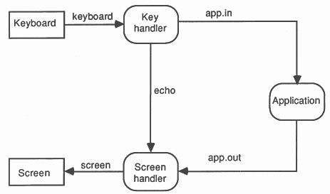
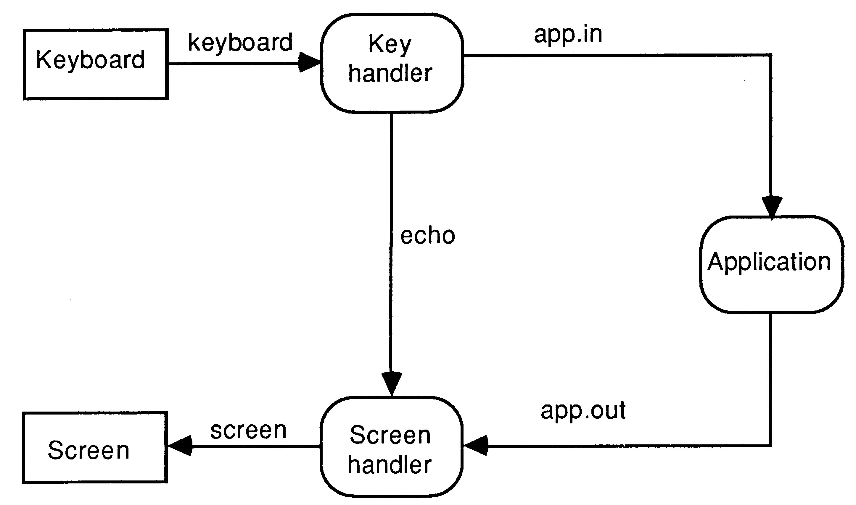
We can now consider the topology of the system. Processes are represented by rounded boxes, and communication channels by arrowed lines. To illustrate a simple case, consider the example in Figure 1.
This shows a functional division of a generic application into a keyboard handler, a screen handler and the application itself. Such a division is for ease of programming and flexibility rather than performance.
Each channel is given a name on the diagram, and then the top level occam can be written. The three functional blocks execute at the same time, i.e. in PARallel. The ONLY items they share are the channels between them, so these are declared in an outer scope.
... proc decls
CHAN OF INT app.in, echo, app.out PAR keyboard.handler( keyboard, app.in, echo ) screen.handler ( screen, app.out, echo ) application ( app.in, app.out ) |
This top level design done - and instantly coded due to the correlation between the occam and the diagram - we progress to the three functional blocks.
These are totally independent, and as long as they agree on the form of data to pass between them, can be designed by different people on different sites. This hierarchical approach means that the most complex task can be attacked and reduced to simplicity.
The last example illustrated functional division. This is the most effective solution for ease of programming, but relies on a divisible task. For the indivisible task, the solution is ”many hands make light work” - achieved by distributing data items to different processors, all working at the same time. In the first example, the system topology was dictated by the connectivity required by the functions. In the indivisible task, the topology is arbitrary.
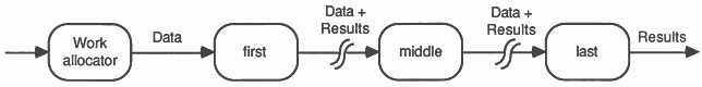
A simple topology directly supported by occam’s PAR replicator syntax is a pipeline, or spaceline. The pipeline relies on each stage not only processing, but also passing on data and/or results on behalf of other processes.
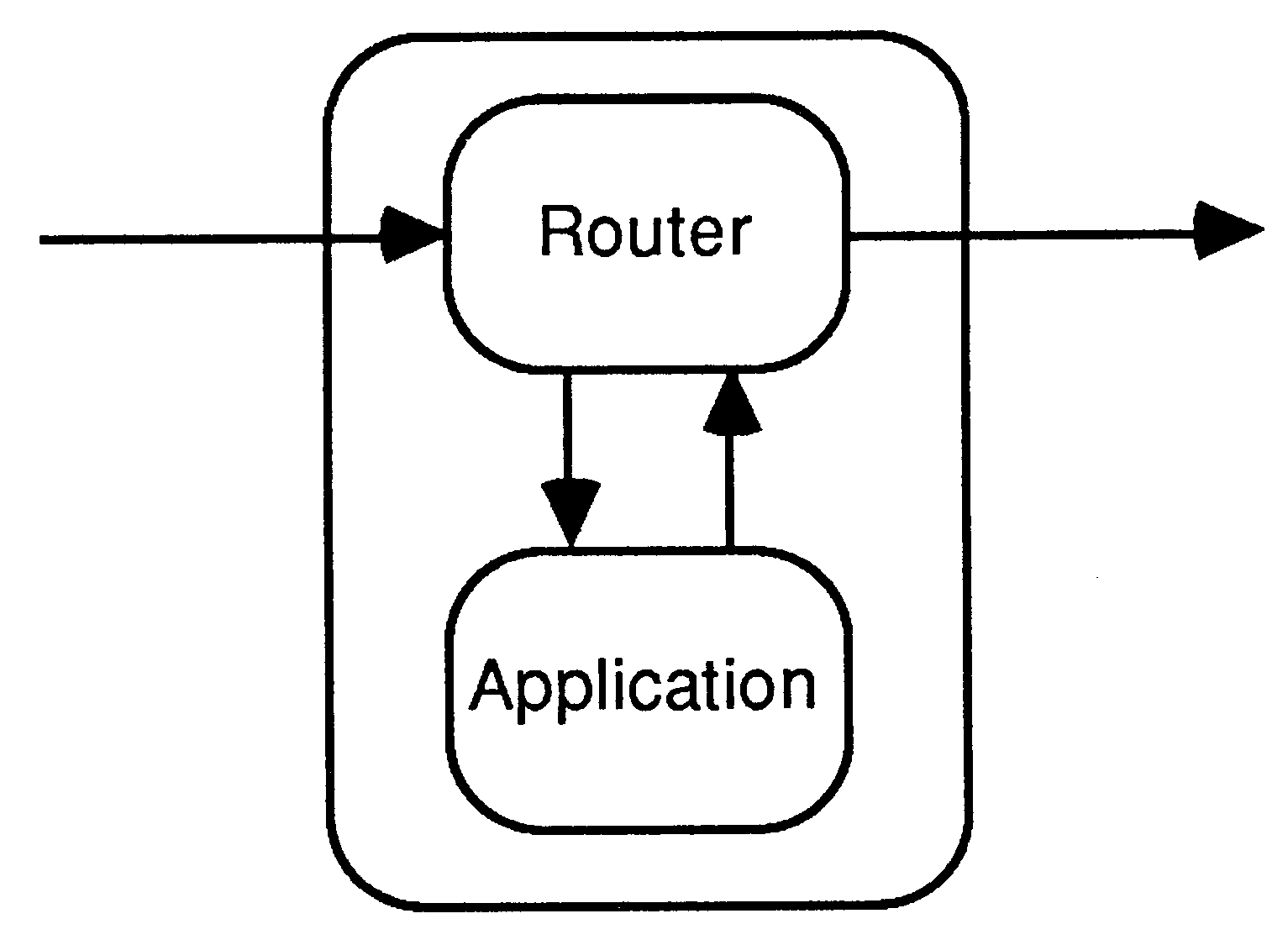
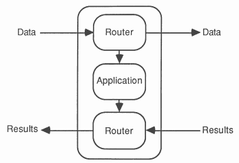
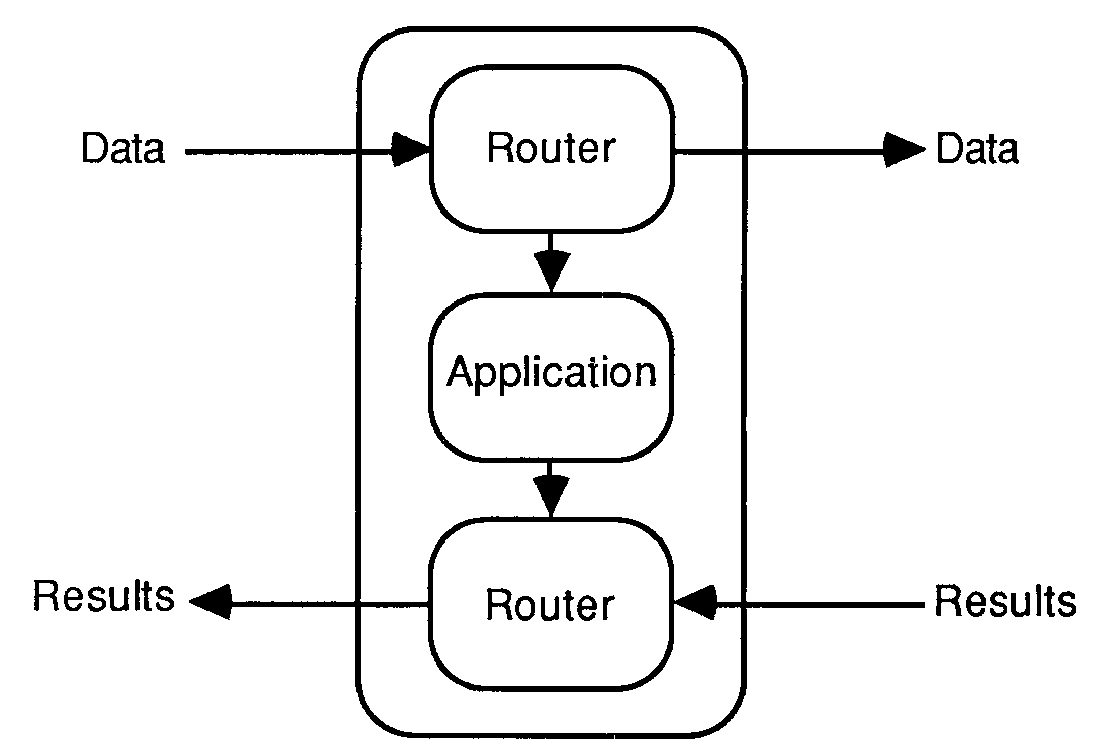
In order to achieve this, messages would have tags indicating their types and a router process would handle this, so each stage would become
However, as channels are available in the opposite direction, one can arrange for input and output to be at one end of the pipeline, which allows for simple extensibility.
The routers are very simple - usually around 5 lines of operational code after initialisation etc, so are not a problem. However, it must be borne in mind that the first processors will be handling the data and results for ALL processors, so one must consider the balance of communications and processing. Provided messages are used, rather than single words or bytes, a pipeline is appropriate to length of order 10 (i.e. < 100)
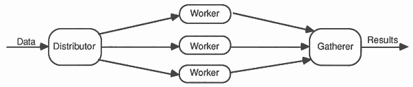
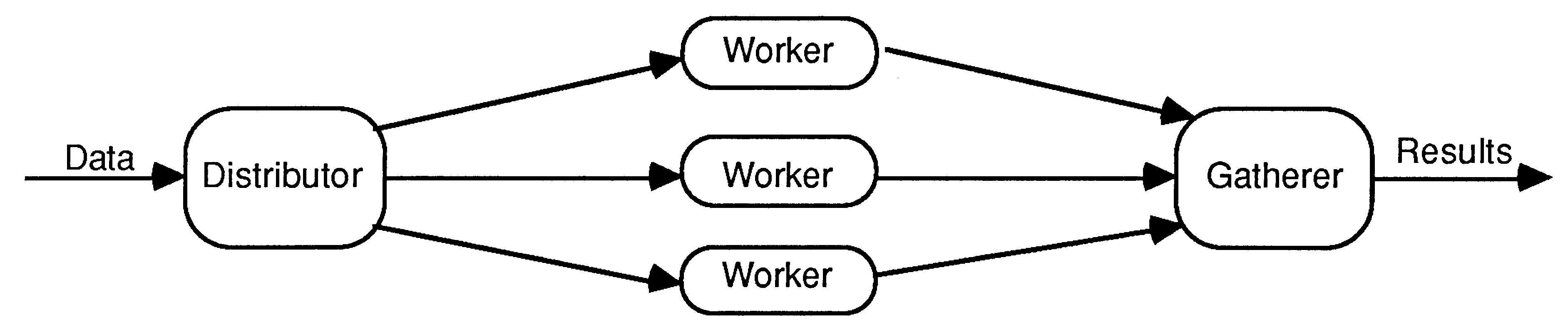
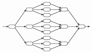
A spaceline system is implemented as shown:
The width of a spaceline is limited by the number of links on the distributor and gatherer. By using a tree structure, spacelines of any width can be constructed.
Clearly, the optimum topology is application dependent, and each application must be judged on its merits. The rest of this note will concentrate on functionally divided applications. For arrays etc. (See Technical Note 13.)
Reverting to the example of figure 1, we must now design the functional blocks.
In general, each process must do some initialisation, then will repetitively receive data, and act upon it. The actions may be complex, may read more data, may generate output, and may terminate the process, but the basic structure still holds.
The Transputer Development System uses a folding editor, which can represent a large block of text in a single named fold line marked by three dots. A fold can contain another fold, nested to any depth. Folds can be ’opened’ by the editor to display internal structure and source text, or ’closed’ to hide data not currently of interest. Thus any level of detail can be viewed at will.
Folds can be created and named even before their contents have been written. This allows the structure of the process to be entered as part of the design. Thus the generic process is as shown here :
PROC my.proc( parameters )
... declarations, including local procs SEQ ... initialisation WHILE condition SEQ ... loop initialise ... input data ... act upon it ... tidy up this pass ... tidy up process : |
Considerable experience training programmers new to both the folding editor and occam has shown that adopting this type of structure is essential, otherwise they immediately enter a program that mimics languages they are accustomed to, rather than making use of the parallel and communications of occam.
Thus the keyboard handler from the example becomes:
PROC keyboard.handler( CHAN OF INT in , out , to.screen)
INT ch: --declarations VAL stopch IS INT ’@’: BOOL running: SEQ running := TRUE --initialisation WHILE running SEQ in ? ch --input PAR --action out ! ch to.screen ! ch IF ch = stopch running = FALSE TRUE SKIP : |
As can be seen, many of the elements of the standard structure are null, but the conscious decision to exclude them is very beneficial in the design process.
One powerful construct of occam that does not clearly fit this structure is the ALTernate. This is used to take input from one of many channels, when it is not known which will be ready first. Thus it is used in the screen handler. The reason it does not clearly fit the standard format is because it includes both input and action. The screen handler implemented here puts echoed text and output text in two separate windows, so the structure is modified to:
WHILE <condition>
ALT ... input from echo SEQ ... go to echo cursor position ... output text ... update cursor position ... input from application SEQ ... go to application cursor position ... output text ... update cursor position |
Again the editor helps, because due to the similarity between the two branches, only one need be entered, it can then be copied and edited.
Once all three function blocks are entered, the system can be compiled and tested. Were it a complex application, the individual processes would have been separately tested, with test-data-generators, as per Technical Note 2. This example, however is simple enough that the complete system can be tested together.The modus operandi is first to run the program on a single transputer, either the development system or an external evaluation board, and then to adapt it for the target system. To adapt this program to run on 3 transputers is mechanical - one simply exchanges the PAR for a PLACED PAR, add PROCESSOR statements, assign the channel names to particular links using PLACE ... AT, and make each PROC separately compiled.
... SC keyboard.handler
... SC screen.handler ... SC application CHAN OF INT keyboard, screen, echo, app.in, app.out: PLACED PAR PROCESSOR 0 T4 PLACE keyboard AT link0in: PLACE echo AT linklout: PLACE app.in AT link2out: keyboard.handler( keyboard, app.in, echo ) PROCESSOR 1 T4 PLACE screen AT link0out: PLACE echo AT linklin: PLACE app.out AT link2in: screen.handler( screen, app.out, echo ) PROCESSOR 2 T4 PLACE app.in AT link0in: PLACE app.out AT linklout: application( app.in, app.out ) |
However, in a more general system, if my advice was heeded, there are more logical processes than physical processors. The allocation must be done by the programmer considering three factors:
Once the decision is taken, it is simply an additional box drawn on the diagram to map our example onto 2 processors.
In this case there is a little juggling to be done to ensure that the code for each processor is a single separately compiled unit.
... SC keyboard.and.screen.handler
... SC application CHAN OF INT keyboard, screen, app.in, app.out: PLACED PAR PROCESSOR 0 T4 PLACE keyboard AT link0in: PLACE screen AT link0out: PLACE app.in AT linklout: PLACE app.out AT linklin: keyboard.and.screen.handler( keyboard, screen, app.in, app.out ) PROCESSOR 1 T4 PLACE app.in AT link0in: PLACE app.out AT link0out: application( app.in, app.out ) |
For the multi transputer system, an additional operation is performed after the compilation known as configuring. This creates a code file that can be loaded into a network of transputers. It includes the routing information for the code, derived from the PROCESSOR and PLACE AT statements. The target system can then be loaded with a single keystroke, and live testing can begin - the multi processor concurrent program is running.
Concurrent programming is very simple, and errors easily avoided, using OCCAM, provided the programmer is willing to adapt his style appropriately. Specification, design and programming become a smooth flow of work using the same tools on the same text, which becomes progressively more detailed. The process and channel diagram is essential in top down design, and at the lower levels, a formalised approach to design, using the folds where a COBOL programmer might have used flow charts allows on-screen design and rapid, error free programming.