|
|
| Transputer networks using the IMS B003 _____________________________________________________________________ |
| Glenn Hill February 1987 |
Each B003 has four transputers connected in as ring as shown in figure 1. There are therefore two links per transputer which can be connected externally. The purpose of this application note is to show that there are a wide variety of networks that can be configured using only B003 boards. In each example given, the same arbitrary process (node), which has not been defined is extracted to all transputers in the network. This of course may not generally be the case, but it is not difficult to modify the program examples to extract separately defined SC procs to individual transputers. For some of the configurations it is necessary to define a mapping function. This simply returns an integer in the range 0..3 which indicates which of the transputers (figure 1) on the B003 is being extracted to. This is necessary since an occam channel will be placed at a different hard link address according to its position in the B003 ring.
In general, in each configuration, arrays of channels are declared and each channel within these arrays is placed at two link addresses (one input and one output) of two different transputers which are connected to each other. The appropriate index for the array of channels, like the mapping index, is a function of the machine identifier. A mapping array is also declared for input and output channels, which contains a list of link addresses. The mapping index is used to reference these arrays so that the channel can be placed at the correct link address. Having placed the channels in this way, they are passed as parameters to the SC proc for extraction.
A brief explanation is given for each of the examples covered, together with a wiring diagram and an Occam program which can be used to configure the network. Each example may be expanded or reduced to an alternative network dimension by changing the value of n, but n must be even. The wiring diagrams given by the transputer development system are given in an appendix.
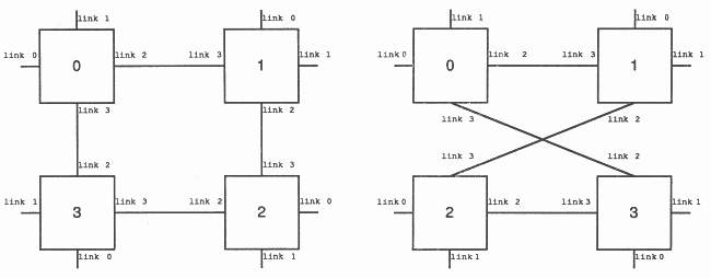
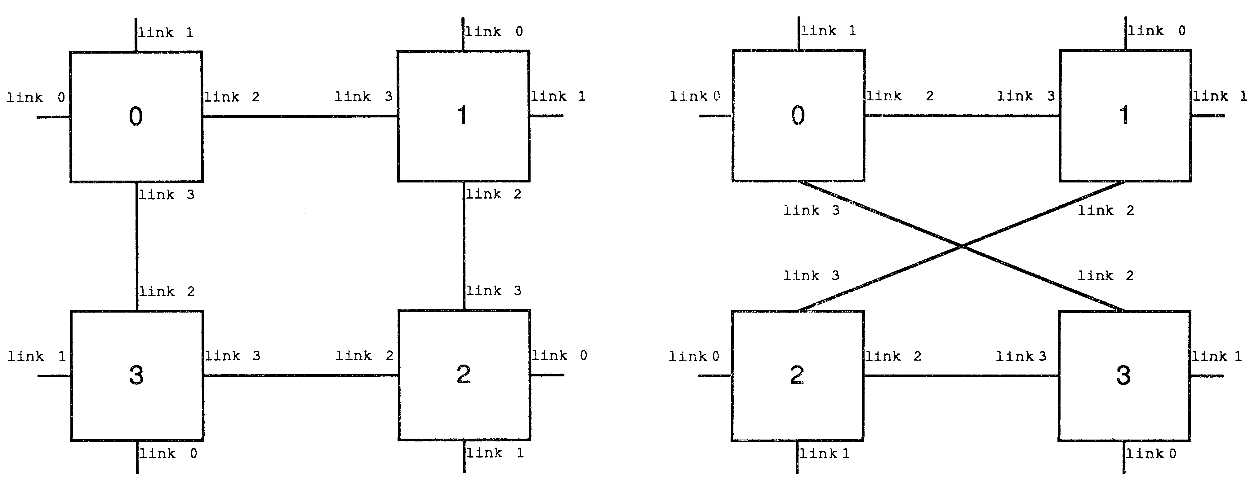
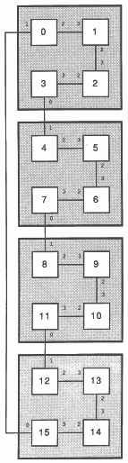
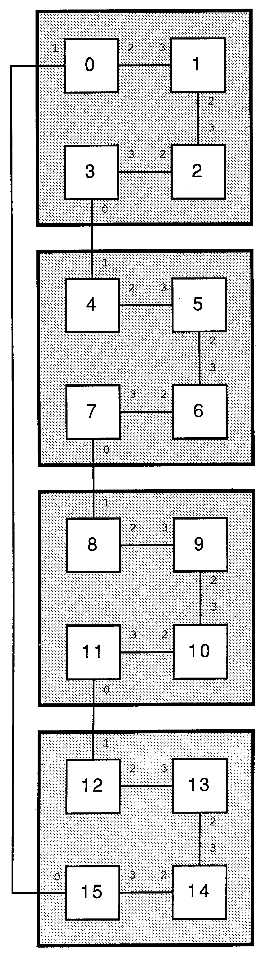
A ring of n transputers can be implemented with n/4 B003 boards. Two arrays of n channels are declared (clockwise and anticlockwise) so that communications around the ring is bidirectional. The transputers are connected as shown in figure 2 (for n = 16), where it can be seen that each machine has a unique identifier in the range 0..(n-1). This identifier is passed as a parameter to the process ”node” together with four channels (two input, two output) from the array of channels, mentioned above.
{{{ 16-node two-directinal ring configured for a B003 application
{{{ define link/channel numbers - T4 VAL link0in IS 4: VAL link0out IS 0: VAL link1in IS 5: VAL link1out IS 1: VAL link2in IS 6: VAL link2out IS 2: VAL link3in IS 7: VAL link3out IS 3: }}} {{{ create internal mapping arrays VAL clockwise.in IS [link1in, link3in, link3in, link3in]: VAL anti.clockwise.in IS [link2in, link2in, link2in, link0in]: VAL clockwise.out IS [link2out, link2out, link2out, link0out]: VAL anti.clockwise.out IS [link1out, link3out, link3out, link3out]: -- each soft channel is associated with a table which is indexed -- when the soft channel is placed on to a hard channel. }}} {{{ declare size of structure VAL n IS 16: -- must be multiple of four VAL nodes IS n: }}} {{{ declare sizes of channels [nodes] CHAN clockwise, anti.clockwise: }}} {{{ SC node -- Separately compiled process "node" to be -- extracted to all nodes. }}} |
{{{ two-directional ring
PLACED PAR machine = 0 FOR nodes PROCESSOR machine T4 {{{ evaluate indices VAL clock.in IS (machine + (nodes-1)) \ nodes: VAL clock.out IS machine: VAL anti.clock.in IS machine: VAL anti.clock.out IS (machine + (nodes-1)) \ nodes: VAL map.index IS machine \ 4: -- position of node within -- B003 group (0..3) }}} {{{ place channels PLACE clockwise [clock.in] AT clockwise.in [map.index]: PLACE clockwise [clock.out] AT clockwise.out [map.index]: PLACE anti.clockwise [anti.clock.in] AT anti.clockwise.in [map.index]: PLACE anti.clockwise [anti.clock.out] AT anti.clockwise.out [map.index]: }}} node ( machine, clockwise [clock.in], clockwise [clock.out], anti.clockwise [anti.clock.in], anti.clockwise [anti.clock.out]) }}} }}} |
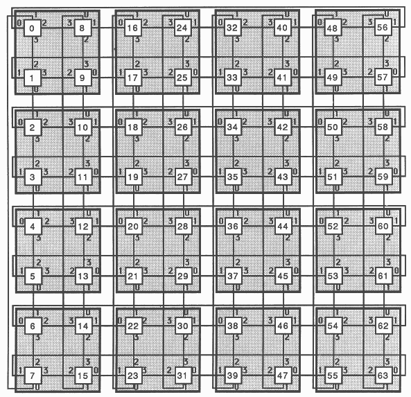
A two dimensional array of (n x n) transputers can be implemented with (n x n) / 4 B003 boards. The configuration should be connected as shown in figure 3 (for n=8). Four arrays of channels (size ”nodes” - number of transputers in network) are declared (left.to.right, right.to.left, top.to.bottom and bottom.to.top), so that each node can send or receive data to or from any of its four neighbours. Eight placed channels (four input, four output) are passed as parameters to the SC proc ”node”. Note that if a square array is not required, p and q can be set to any even number.
{{{ 64-node two-dimensional array configured for a B003 application
{{{ define link/channel numbers - T4 VAL link0in IS 4: VAL link0out IS 0: VAL link1in IS 5: VAL link1out IS 1: VAL link2in IS 6: VAL link2out IS 2: VAL link3in IS 7: VAL link3out IS 3: }}} {{{ create internal mapping arrays VAL left.to.right.in IS [link0in, link3in, link1in, link2in]: VAL right.to.left.in IS [link2in, link1in, link3in, link0in]: VAL top.to.bottom.in IS [link1in, link0in, link2in, link3in]: VAL bottom.to.top.in IS [link3in, link2in, link0in, link1in]: VAL left.to.right.out IS [link2out, link1out, link3out, link0out]: VAL right.to.left.out IS [link0out, link3out, link1out, link2out]: VAL top.to.bottom.out IS [link3out, link2out, link0out, link1out]: VAL bottom.to.top.out IS [link1out, link0out, link2out, link3out]: -- each soft channel is associated with a table which is indexed -- when the soft channel is placed on to a hard channel. }}} {{{ declare size of structure VAL n IS 8: VAL p IS n: -- x dimension of array VAL q IS n: -- y dimension of array VAL nodes IS p * q: }}} {{{ declare sizes channels [nodes] CHAN left.to.right, right.to.left, top.to.bottom, bottom.to.top: }}} {{{ SC node -- Separately compiled process "node" to be -- extracted to all nodes. }}} |
{{{ two-dimensional array (placed)
PLACED PAR i = 0 FOR p PLACED PAR j = 0 FOR q VAL machine IS j + (i * q): PROCESSOR machine T4 {{{ evaluate indices VAL left IS (machine + (nodes-q)) \ nodes: VAL right IS machine: VAL bottom IS machine: VAL dec.j IS (j + (q-1)) \ q: VAL top IS dec.j + (i * q): VAL map.index IS ((j\2)*2) + (i\2): -- position of node within -- B003 group (0..3) }}} {{{ place channels PLACE left.to.right [left] AT left.to.right.in [map.index]: PLACE left.to.right [right] AT left.to.right.out [map.index]: PLACE right.to.left [right] AT right.to.left.in [map.index]: PLACE right.to.left [left] AT right.to.left.out [map.index]: PLACE top.to.bottom [top] AT top.to.bottom.in [map.index]: PLACE top.to.bottom [bottom] AT top.to.bottom.out [map.index]: PLACE bottom.to.top [bottom] AT bottom.to.top.in [map.index]: PLACE bottom.to.top [top] AT bottom.to.top.out [map.index]: }}} node ( machine, left.to.right [left], left.to.right [right], right.to.left [right], right.to.left [left], top.to.bottom [top], top.to.bottom [bottom], bottom.to.top [bottom], bottom.to.top [top]) }}} }}} |
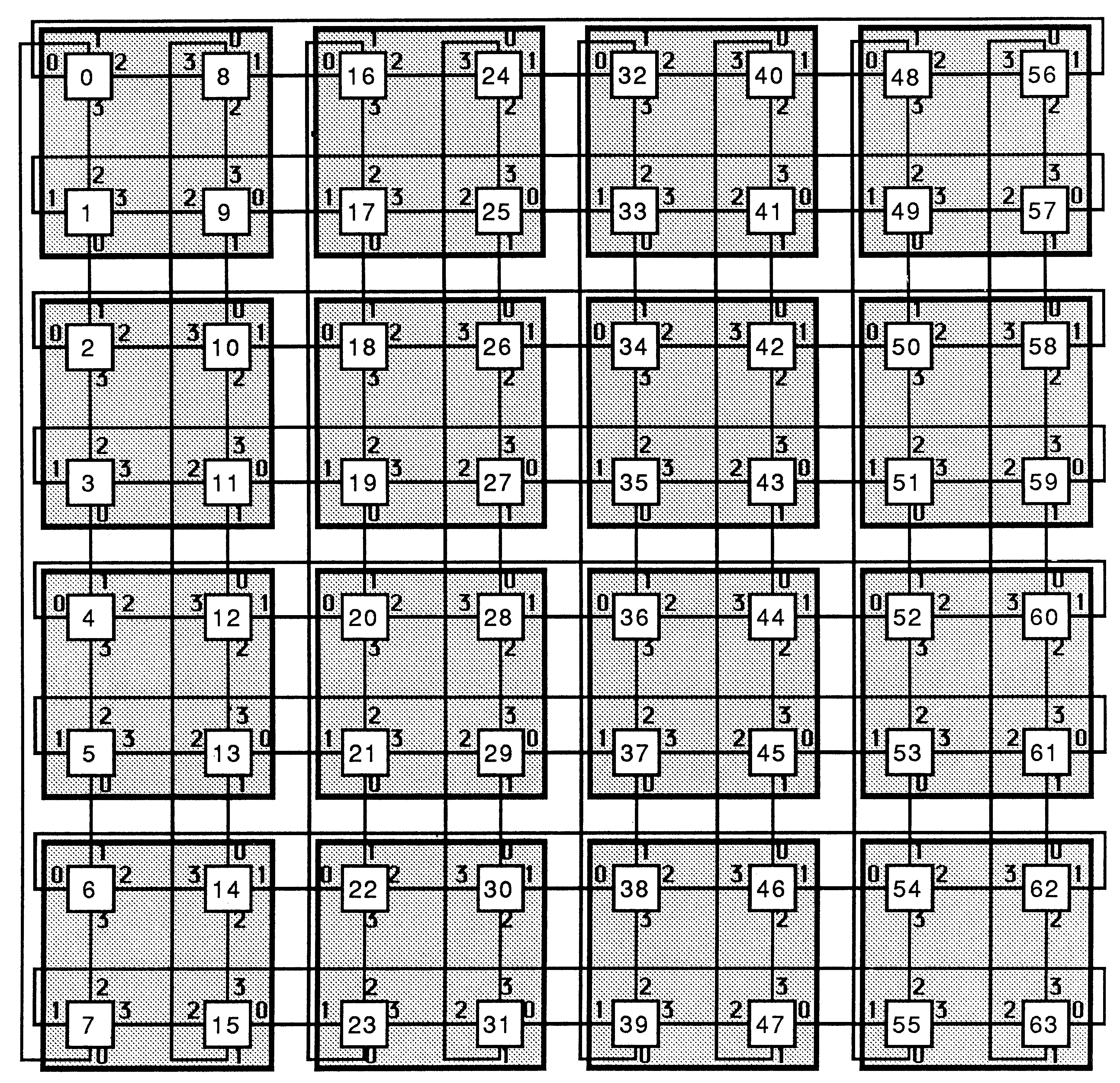
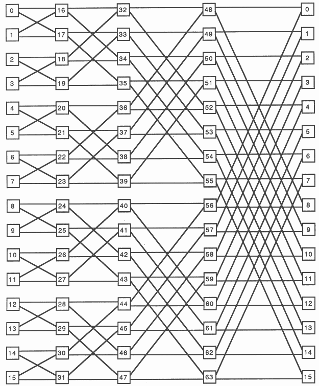
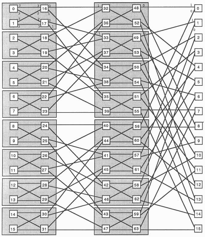
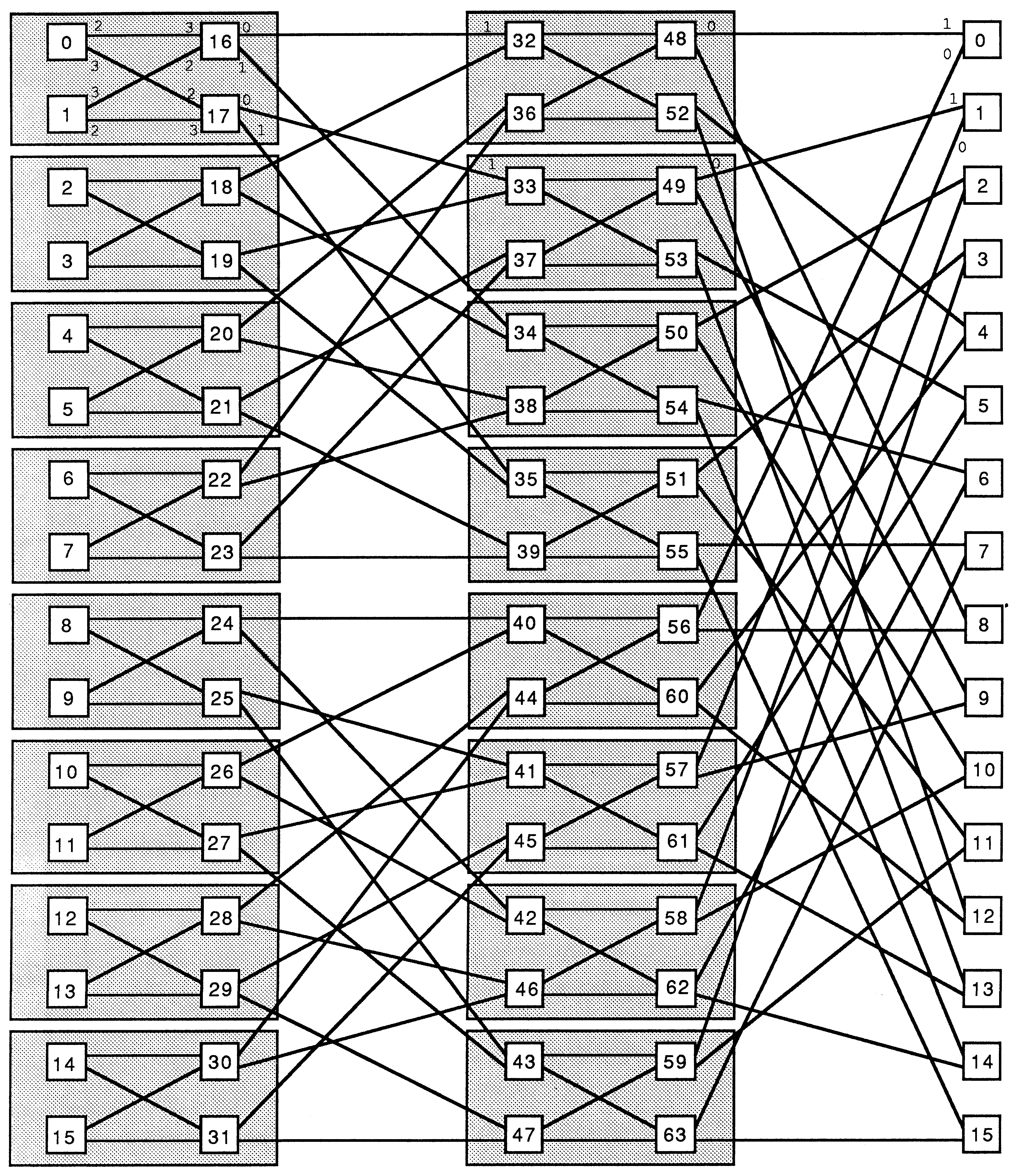
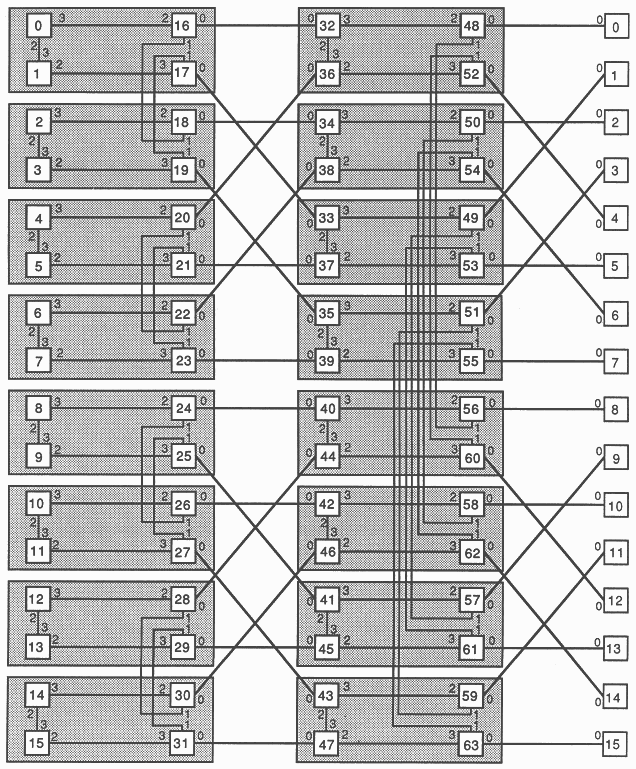
A folded binary structure of size n x 2n can be implemented with (n x 2n) / 4 B003 boards. This configuration should be connected as shown in figures 4 and 5) (for n=4). Note that figures 4 and 5 are topographically equivalent. Figure 5 merely makes it easier to see how the boards are connected externally. Four arrays of channels of dimension ”nodes” (number of transputers in network) are declared: adj.left, adj.right, diag.left and diag.right where ”adj” is a mnemonic for adjacent connection and ”diag” for a diagonal connection. This enables each transputer to send or receive data to or from any of its four neighbours. Eight placed channels (four input, four output) are passed as parameters to the SC proc ”node”.
{{{ 64 node Folded Binary Structure configured for a B003 application
{{{ define link/channel numbers - T4 VAL link0in IS 4: VAL link0out IS 0: VAL link1in IS 5: VAL link1out IS 1: VAL link2in IS 6: VAL link2out IS 2: VAL link3in IS 7: VAL link3out IS 3: }}} {{{ create internal mapping arrays VAL adj.left.in IS [link2in, link0in, link2in, link1in]: VAL adj.right.in IS [link1in, link3in, link1in, link3in]: VAL diag.left.in IS [link3in, link1in, link3in, link1in]: VAL diag.right.in IS [link0in, link2in, link1in, link2in]: VAL adj.left.out IS [link1out, link3out, link1out, link3out]: VAL adj.right.out IS [link2out, link0out, link2out, link1out]: VAL diag.left.out IS [link0out, link2out, link0out, link2out]: VAL diag.right.out IS [link3out, link1out, link3out, link1out]: -- each soft channel is associated with a table which is indexed -- when the soft channel is placed on to a hard channel. }}} {{{ declare size of structure VAL n IS 4: VAL p IS n, -- width of FBS (minimum is 2) q IS (1 << n): -- height of FBS VAL nodes IS p * q: }}} {{{ declare sizes channels [nodes] CHAN adj.left, -- adj = adjacent connection adj.right, -- diag = diagonal connection diag.left, -- left = right to left direction diag.right: -- right = left to right direction }}} {{{ SC node -- Separately compiled process "node" to be -- extracted to all nodes. }}} |
{{{ Folded Binary Structure (placed)
PLACED PAR i = 0 FOR p PLACED PAR j = 0 FOR q VAL this.machine IS j + (i * q): PROCESSOR this.machine T4 {{{ evaluate indices VAL dec.i IS (i + (p-1)) \ p: -- i value of node on LHS VAL a.left IS (dec.i * q) + j: -- index of adjacent -- channel on LHS VAL a.right IS (q * i) + j: -- index of adjacent -- channel on RHS VAL d.root IS a.left: VAL diff IS 1 << dec.i: VAL test.bit IS (j >> dec.i) /\ 1: VAL d.left IS d.root + (diff * (-((test.bit * 2) - 1))): -- index of diagonal -- channel on LHS VAL d.right IS a.right: -- index of diagonal -- channel on RHS VAL group IS (1<<i) >> (i\2): -- size of B003 group in -- which this node is -- interleaved VAL map.index IS (((j\(group<<1))/group)<<1) + (i\2): -- position of node -- within B003 group -- (0..3) }}} {{{ place channels PLACE adj.left [a.right] AT adj.left.in [map.index] PLACE adj.left [a.left] AT adj.left.out [map.index] PLACE adj.right [a.left] AT adj.right.in [map.index] PLACE adj.right [a.right] AT adj.right.out [map.index] PLACE diag.left [d.right] AT diag.left.in [map.index] PLACE diag.left [d.left] AT diag.left.out [map.index] PLACE diag.right [d.left] AT diag.right.in [map.index] PLACE diag.right [d.right] AT diag.right.out [map.index] }}} node ( this.machine, adj.right [a.right], adj.left [a.right], adj.right [a.left], adj.left [a.left], diag.right [d.right], diag.left [d.right], diag.right [d.left], diag.left [d.left]) }}} }}} |
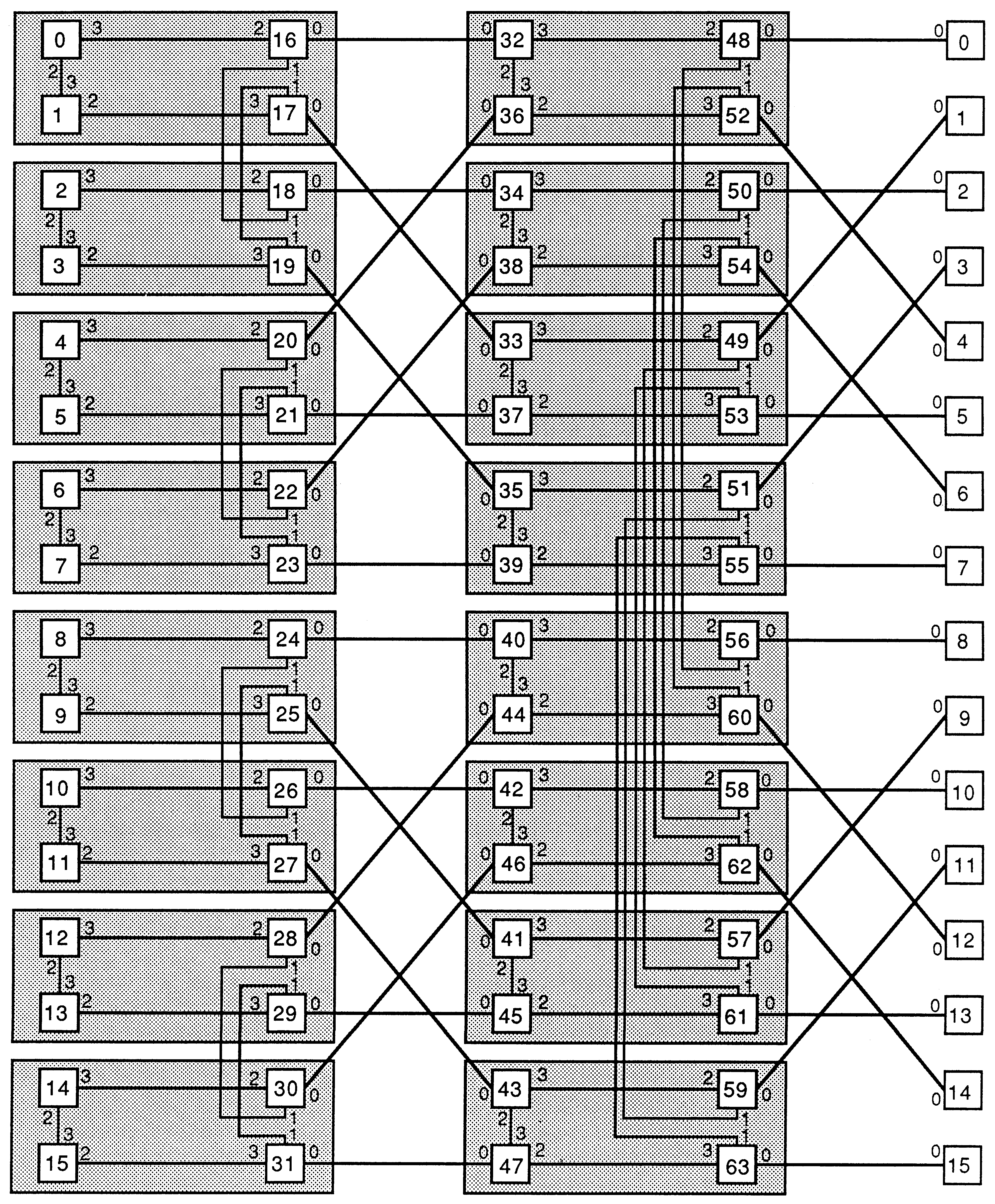
Figure 5 shows how the structure in Figure 4 can be mapped onto 16 B003s.
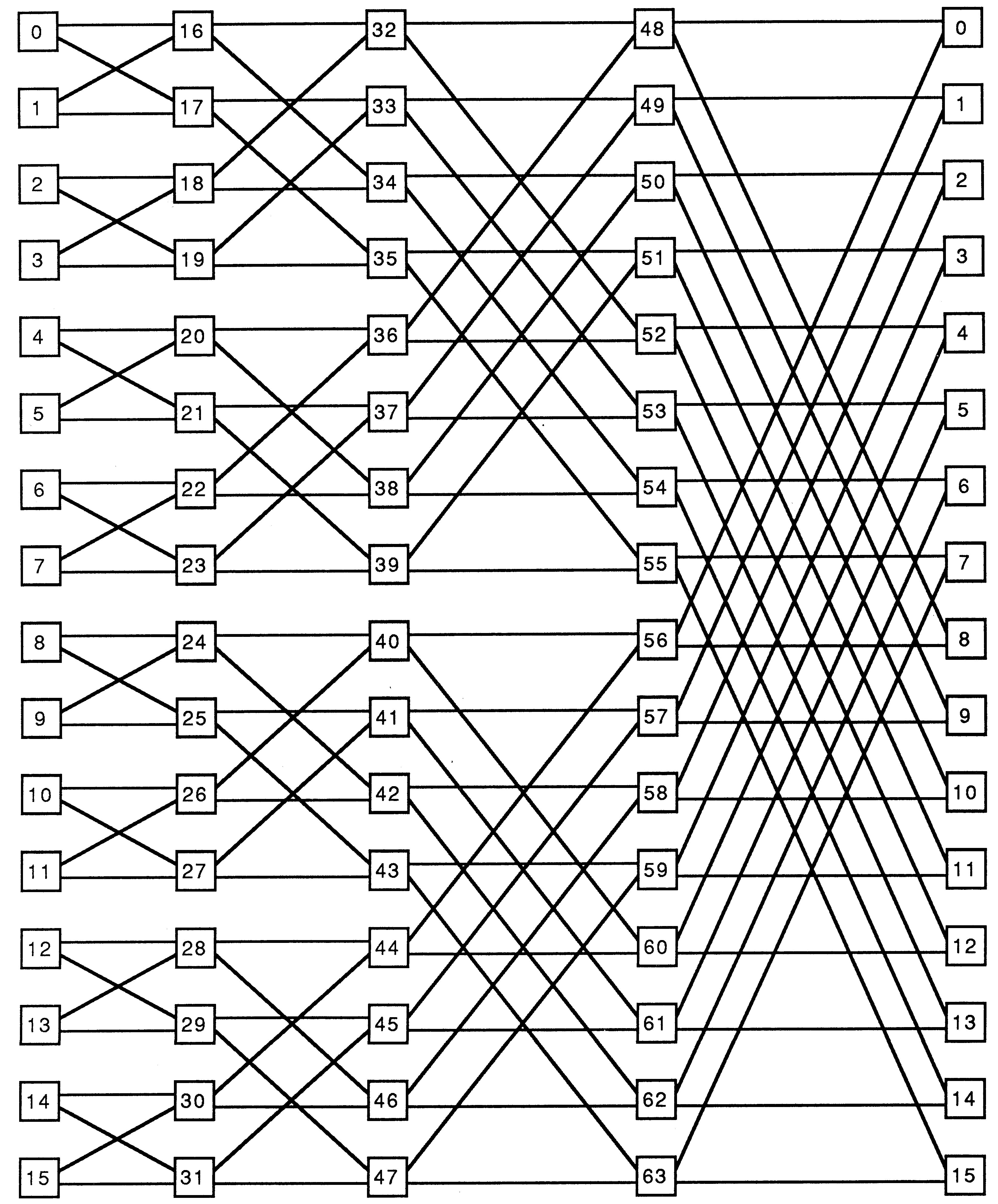
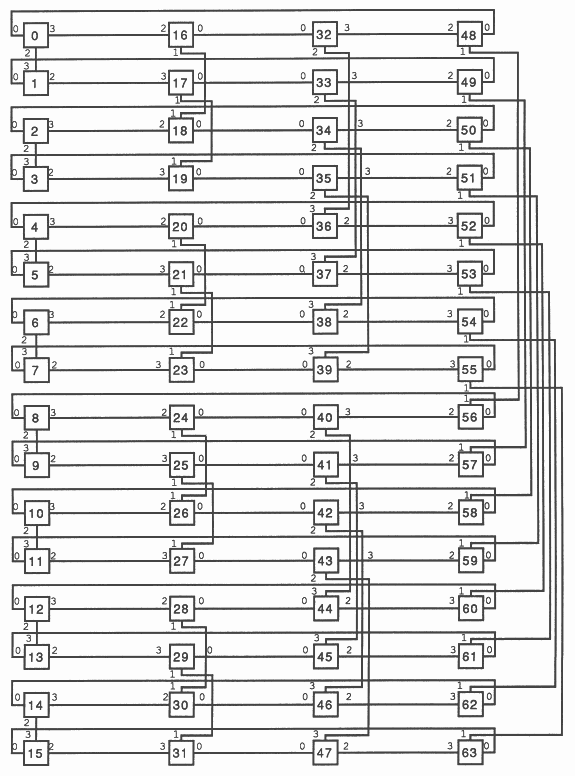
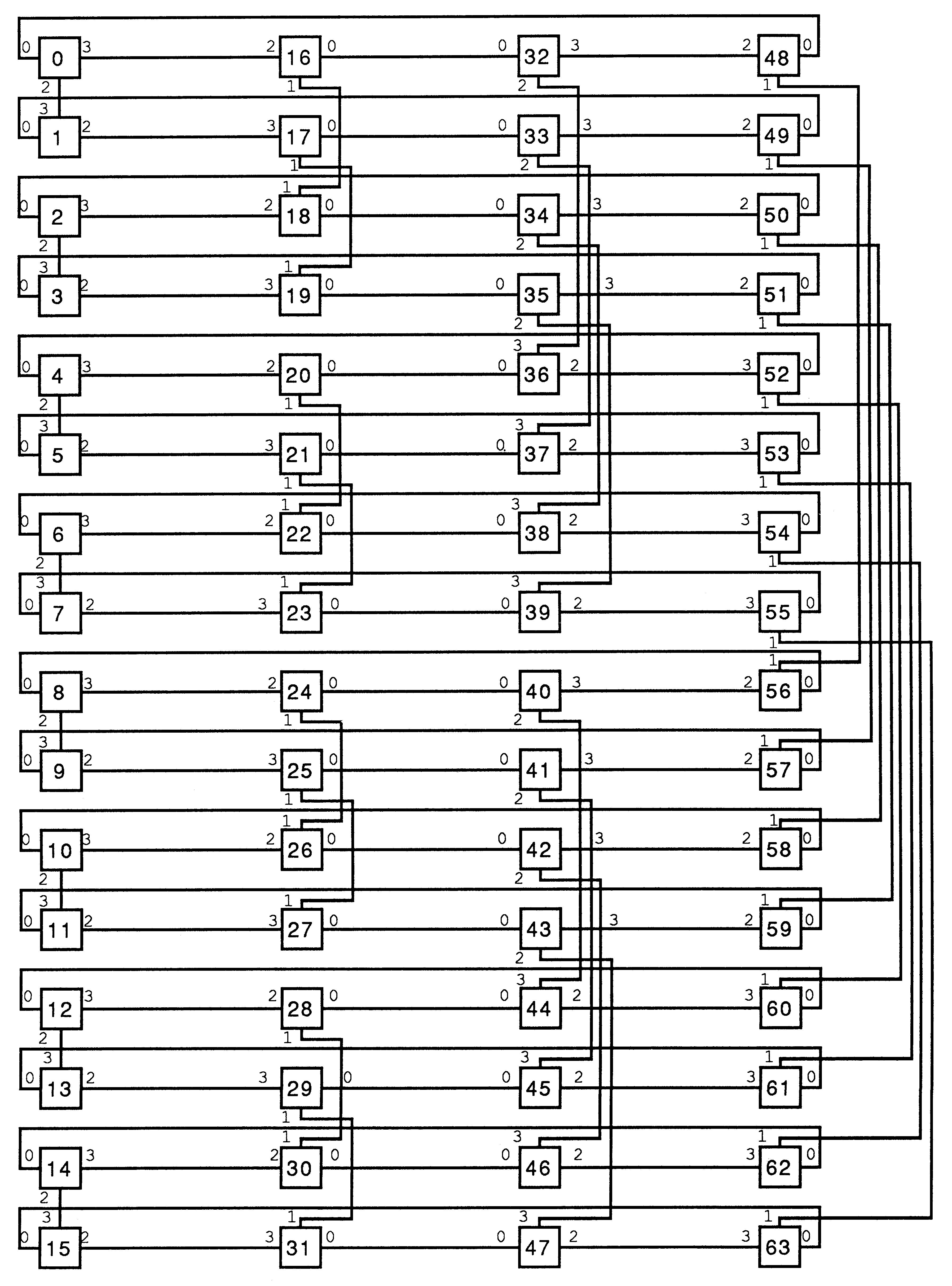
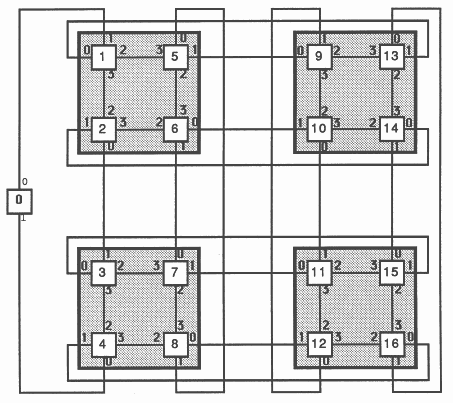
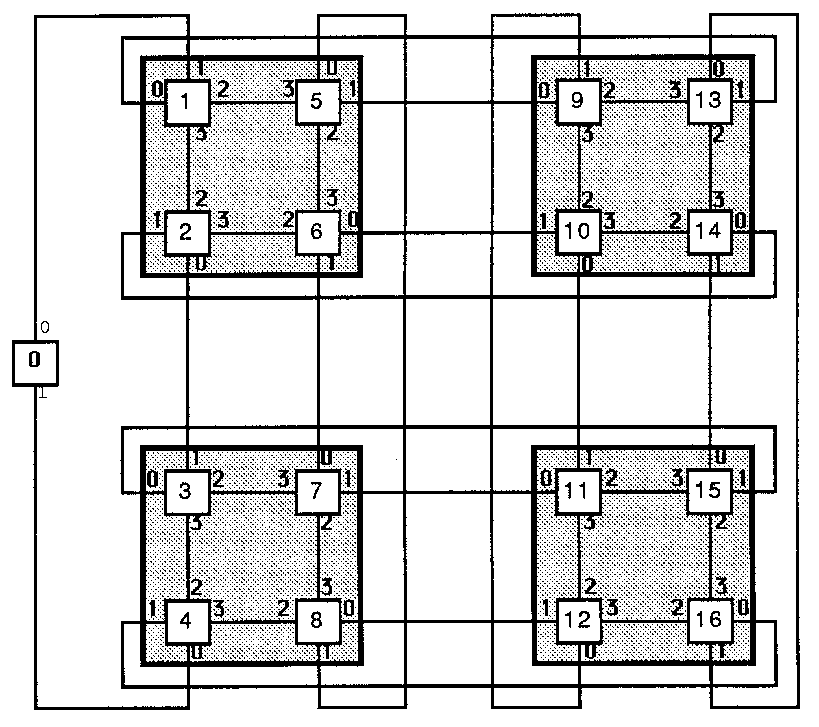
A cube connected cycle of size n x 2n can be implemented with (n x 2n) / 4 B003 boards. A connection diagram for such a network, for n=4, is shown in figures 6 and 7 (Figure 7 shows how nodes map to B003s). Three arrays of channels are declared of dimension ”nodes” (number of transputers in network): clockwise.route, anti.clockwise.route and cross.route, where ”clockwise” and ”anti.clockwise” represent channels connected to nodes in the same row, and ”cross” represents a channel connected to a different row. Figures 6 and 7 are topographically equivalent to a four-dimensional hypercube with four nodes at each ”corner”. Six placed channels (three input, three output) are passed as parameters to the SC proc ”node”.
{{{ 64 node Cube Connected Cycle (3-link)- B003 configuration
{{{ define link/channel numbers - T4 VAL link0in IS 4: VAL link0out IS 0: VAL link1in IS 5: VAL link1out IS 1: VAL link2in IS 6: VAL link2out IS 2: VAL link3in IS 7: VAL link3out IS 3: }}} {{{ declare size of structure VAL p IS 6, -- width of CCC (minimum is 2) q IS (1 << p): -- height of CCC VAL nodes IS p * q: }}} {{{ declare sizes channels [nodes] CHAN clockwise.route, -- clockwise cycle links anti.clockwise.route, -- anti-clockwise cycle links cross.route: -- cross links to other dimensions }}} {{{ create internal mapping arrays VAL clockwise.in.map IS [link0in, link0in, link2in, link3in]: VAL anti.clockwise.in.map IS [link3in, link2in, link0in, link0in]: VAL cross.in.map IS [link2in, link3in, link1in, link1in]: VAL clockwise.out.map IS [link3out, link2out, link0out, link0out]: VAL anti.clockwise.out.map IS [link0out, link0out, link2out, link3out]: VAL cross.out.map IS [link2out, link3out, link1out, link1out]: -- each soft channel has a table which is indexed -- when the soft channel is placed on to a hard channel. }}} {{{ SC node -- Separately compiled process to be -- extracted to all nodes. }}} |
{{{ Cube-connected Cycle
PLACED PAR ring.pos = 0 FOR p PLACED PAR co.ord = 0 FOR q VAL this.machine IS co.ord + (ring.pos * q): PROCESSOR this.machine T4 {{{ define indices and value parameters for process call VAL dec.ring.pos IS (ring.pos + (p -1)) \ p: -- ring.pos value of node on LHS VAL inc.ring.pos IS (ring.pos + 1) \ p: -- ring.pos value of node on RHS VAL machine IS (q * ring.pos) + co.ord: -- node identifier VAL clockwise.in IS (q * dec.ring.pos) + co.ord: -- index for clockwise.route on LHS VAL anti.clockwise.in IS (q * inc.ring.pos) + co.ord: -- index for anti.clockwise.route on RHS VAL clockwise.out IS machine: -- index for clockwise.route on RHS VAL anti.clockwise.out IS machine: -- index for anti.clockwise.route on LHS VAL cross.in IS (co.ord >< (1<<ring.pos)) + (q * ring.pos): VAL cross.out IS machine: -- indices for cross.route VAL map.index IS ((ring.pos\2)*2): + ((co.ord/(1<<(2*(ring.pos/2))))\2): }}} {{{ place channels PLACE anti.clockwise.route [anti.clockwise.out] AT anti.clockwise.out.map [map.index]: PLACE clockwise.route [clockwise.in] AT clockwise.in.map [map.index]: PLACE anti.clockwise.route [anti.clockwise.in] AT anti.clockwise.in.map [map.index]: PLACE clockwise.route [clockwise.out] AT clockwise.out.map [map.index]: PLACE cross.route [cross.out] AT cross.out.map [map.index]: PLACE cross.route [cross.in] AT cross.in.map [map.index]: }}} node ( machine, anti.clockwise.route [anti.clockwise.out], clockwise.route [clockwise.in], anti.clockwise.route [anti.clockwise.in], clockwise.route [clockwise.out], cross.route [cross.out], cross.route [cross.in]) }}} }}} |
For the configurations above which use all four links of every transputer, there is no provision for booting the code which on a B003 board must be done via a transputer link. The problem has been avoided so far since it destroys the symmetry of the network and makes the program unnecessarily complicated for these introductory examples. For completeness, this chapter shows one way that the problem may be solved for a 16 node two-dimensional array. An extra transputer, which may be on a B001 or B002 board, is used as the boot node which can be connected via a UART to a host machine. This processor is by convention node 0, which means that the identifier of all other nodes must be incremented by one (figure 8).
{{{
{{{ define link/channel numbers - T4 VAL link0in IS 4: VAL link0out IS 0: VAL link1in IS 5: VAL link1out IS 1: VAL link2in IS 6: VAL link2out IS 2: VAL link3in IS 7: VAL link3out IS 3: }}} {{{ create internal mapping arrays VAL left.to.right.in IS [link0in, link3in, link1in, link2in]: VAL right.to.left.in IS [link2in, link1in, link3in, link0in]: VAL top.to.bottom.in IS [link1in, link0in, link2in, link3in]: VAL bottom.to.top.in IS [link3in, link2in, link0in, link1in]: VAL left.to.right.out IS [link2out, link1out, link3out, link0out]: VAL right.to.left.out IS [link0out, link3out, link1out, link2out]: VAL top.to.bottom.out IS [link3out, link2out, link0out, link1out]: VAL bottom.to.top.out IS [link1out, link0out, link2out, link3out]: -- each soft channel is associated with a table which is indexed -- when the soft channel is placed on to a hard channel. }}} {{{ declare size of structure VAL n IS 4: VAL p IS n: -- x dimension of array VAL q IS n: -- y dimension of array VAL nodes IS p * q: }}} {{{ declare sizes channels [nodes] CHAN left.to.right, right.to.left: [nodes + 1] CHAN top.to.bottom, bottom.to.top: }}} {{{ SC root.node -- Separately compiled process "root.node" -- to be extracted to node 0. }}} {{{ SC node -- Separately compiled process "node" to be -- extracted to all other nodes. }}} |
-- "machine" is the node identifier.
-- "dec.machine" is one less than the node identifier and is used -- to index the arrays of channels that link the nodes PLACED PAR {{{ root node {{{ declare constant indices VAL bottom IS q-1: VAL top IS nodes: }}} PROCESSOR 0 T4 {{{ place channels PLACE top.to.bottom [top] AT link0out: PLACE top.to.bottom [bottom] AT link1in: PLACE bottom.to.top [bottom] AT link1out: PLACE bottom.to.top [top] AT link0in: }}} root.node ( top.to.bottom [top], top.to.bottom [bottom], bottom.to.top [bottom], bottom.to.top [top]) }}} {{{ node 1 {{{ declare constant indices VAL i IS 0: VAL j IS 0: VAL dec.machine IS 0: VAL left IS (dec.machine + (nodes-q)) \ nodes: VAL right IS dec.machine: VAL bottom IS dec.machine: VAL top IS nodes: VAL map.index IS ((j\2)*2) + (i\2): }}} PROCESSOR 1 T4 {{{ place channels PLACE left.to.right [left] AT left.to.right.in [map.index]: PLACE left.to.right [right] AT left.to.right.out [map.index]: PLACE right.to.left [right] AT right.to.left.in [map.index]: PLACE right.to.left [left] AT right.to.left.out [map.indexr: PLACE top.to.bottom [top] AT top.to.bottom.in [map.index]: PLACE top.to.bottom [bottom] AT top.to.bottom.out [map.index]: PLACE bottom.to.top [bottom] AT bottom.to.top.in [map.index]: PLACE bottom.to.top [top] AT bottom.to.top.out [map.indexl: }}} node ( 1, left.to.right [left], left.to.right [right], right.to.left [right], right.to.left [left], top.to.bottom [top], top.to.bottom [bottom], bottom.to.top [bottom], bottom.to.top [top]) }}} {{{ node q {{{ declare constant indices VAL i IS 0: VAL j IS q-1: VAL dec.machine IS q-1: VAL left IS (dec.machine + (nodes-q)) \ nodes: VAL right IS dec.machine: VAL bottom IS dec.machine: VAL dec.j IS (j + (q-1)) \ q: VAL top IS dec.j + (i * q): VAL map.index IS ((j\2)*2) + (i\2): }}} PROCESSOR q T4 {{{ place channels PLACE left.to.right [left] AT left.to.right.in [map.index]: PLACE left.to.right [right] AT left.to.right.out [map.index]: PLACE right.to.left [right] AT right.to.left.in [map.index]: PLACE right.to.left [left] AT right.to.left.out [map.index]: PLACE top.to.bottom [top] AT top.to.bottom.in [map.index]: PLACE top.to.bottom [bottom] AT top.to.bottom.out [map.index]: PLACE bottom.to.top [bottom] AT bottom.to.top.in [map.index]: PLACE bottom.to.top [top] AT bottom.to.top.out [map.index]: }}} node ( q, left.to.right [left], left.to.right [right], right.to.left [right], right.to.left [left], top.to.bottom [top], top.to.bottom [bottom], bottom.to.top [bottom], bottom.to.top [top]) }}} VAL i IS 0: PLACED PAR j = 1 FOR (q-2) VAL dec.machine IS j + (i * q): VAL machine IS dec.machine + 1: PROCESSOR machine T4 {{{ evaluate indices VAL left IS (dec.machine + (nodes-q)) \ nodes: VAL right IS dec.machine: VAL bottom IS dec.machine: VAL dec.j IS (j + (q-1)) \ q: VAL top IS dec.j + (i * q): VAL map.index IS ((j\2)*2) + (i\2): -- position of node within -- B003 group (0-3) }}} {{{ place channels PLACE left.to.right [left] AT lert.to.right.in [map.index]: PLACE left.to.right [right] AT left.to.right.out [map.index]: PLACE right.to.left [right] AT right.to.left.in [map.index]: PLACE right.to.left [left] AT right.to.left.out [map.index]: PLACE top.to.bottom [top] AT top.to.bottom.in [map.index]: PLACE top.to.bottom [bottom] AT top.to.bottom.out [map.index]: PLACE bottom.to.top [bottom] AT bottom.to.top.in [map.index]: PLACE bottom.to.top [top] AT bottom.to.top.out [map.index]: }}} node ( machine, left.to.right [left], left.to.right [right], right.to.left [right], right.to.left [left], top.to.bottom [top], top.to.bottom [bottom], bottom.to.top [bottom], bottom.to.top [top]) PLACED PAR i = 1 FOR (p-1) PLACED PAR j = 0 FOR q VAL dec.machine IS j + (i * q): VAL machine IS dec.machine + 1: PROCESSOR machine T4 {{{ evaluate indices VAL left IS (dec.machine + (nodes-q)) \ nodes: VAL right IS dec.machine: VAL bottom IS dec.machine: VAL dec.j IS (j + (q-1)) \ q: VAL top IS dec.j + (i * q): VAL map.index IS ((j\2)*2) + (i\2): -- position of node -- within -- B003 group (0..3) }}} {{{ place channels PLACE left.to.right [left] AT left.to.right.in [map.index]: PLACE left.to.right [right] AT left.to.right.out [map.index]: PLACE right.to.left [right] AT right.to.left.in [map.index]: PLACE right.to.left [left] AT right.to.left.out [map.index]: PLACE top.to.bottom [top] AT top.to.bottom.in [map.index]: PLACE top.to.bottom [bottom] AT top.to.bottom.out [map.index]: PLACE bottom.to.top [bottom] AT bottom.to.top.in [map.index]: PLACE bottom.to.top [top] AT bottom.to.top.out [map.index]: }}} node ( machine, left.to.right [left], left.to.right [right], right.to.left [right], right.to.left [left], top.to.bottom [top], top.to.bottom [bottom], bottom.to.top [bottom], bottom.to.top [top]) }}} |
This appendix includes the wiring diagrams that have been created with the transputer development system (TDS) for the previous examples. Only link 0 and link 1 connections have been included since links 2 and 3 are internally connected on the B003 board.
{{{ wiring diagram
Connectivity Diagram -------------------- occam 2 connect processor 0 link 1 to processor 15 link 0 connect processor 3 link 0 to processor 4 link 1 connect processor 7 link 0 to processor 8 link 1 connect processor 11 link 0 to processor 12 link 1 }}} |
{{{ wiring diagram
Connectivity Diagram -------------------- occam 2 connect processor 0 link 0 to processor 56 link 1 connect processor 0 link 1 to processor 7 link 0 connect processor 1 link 0 to processor 2 link 1 connect processor 1 link 1 to processor 57 link 0 connect processor 2 link 0 to processor 58 link 1 connect processor 3 link 0 to processor 4 link 1 connect processor 3 link 1 to processor 59 link 0 connect processor 4 link 0 to processor 60 link 1 connect processor 5 link 0 to processor 6 link 1 connect processor 5 link 1 to processor 61 link 0 connect processor 6 link 0 to processor 62 link 1 connect processor 7 link 1 to processor 63 link 0 connect processor 8 link 0 to processor 15 link 1 connect processor 8 link 1 to processor 16 link 0 connect processor 9 link 0 to processor 17 link 1 connect processor 9 link 1 to processor 10 link 0 connect processor 10 link 1 to processor 18 link 0 connect processor 11 link 0 to processor 19 link 1 connect processor 11 link 1 to processor 12 link 0 connect processor 12 link 1 to processor 20 link 0 connect processor 13 link 0 to processor 21 link 1 connect processor 13 link 1 to processor 14 link 0 connect processor 14 link 1 to processor 22 link 0 connect processor 15 link 0 to processor 23 link 1 connect processor 16 link 1 to processor 23 link 0 connect processor 17 link 0 to processor 18 link 1 connect processor 19 link 0 to processor 20 link 1 connect processor 21 link 0 to processor 22 link 1 connect processor 24 link 0 to processor 31 link 1 connect processor 24 link 1 to processor 32 link 0 connect processor 25 link 0 to processor 33 link 1 connect processor 25 link 1 to processor 26 link 0 connect processor 26 link 1 to processor 34 link 0 connect processor 27 link 0 to processor 35 link 1 connect processor 27 link 1 to processor 28 link 0 connect processor 28 link 1 to processor 36 link 0 connect processor 29 link 0 to processor 37 link 1 connect processor 29 link 1 to processor 30 link 0 connect processor 30 link 1 to processor 38 link 0 connect processor 31 link 0 to processor 39 link 1 connect processor 32 link 1 to processor 39 link 0 connect processor 33 link 0 to processor 34 link 1 connect processor 35 link 0 to processor 36 link 1 connect processor 37 link 0 to processor 38 link 1 connect processor 40 link 0 to processor 47 link 1 connect processor 40 link 1 to processor 48 link 0 connect processor 41 link 0 to processor 49 link 1 connect processor 41 link 1 to processor 42 link 0 connect processor 42 link 1 to processor 50 link 0 connect processor 43 link 0 to processor 51 link 1 connect processor 43 link 1 to processor 44 link 0 connect processor 44 link 1 to processor 52 link 0 connect processor 45 link 0 to processor 53 link 1 connect processor 45 link 1 to processor 46 link 0 connect processor 46 link 1 to processor 54 link 0 connect processor 47 link 0 to processor 55 link 1 connect processor 48 link 1 to processor 55 link 0 connect processor 49 link 0 to processor 50 link 1 connect processor 51 link 0 to processor 52 link 1 connect processor 53 link 0 to processor 54 link 1 connect processor 56 link 0 to processor 63 link 1 connect processor 57 link 1 to processor 58 link 0 connect processor 59 link 1 to processor 60 link 0 connect processor 61 link 1 to processor 62 link 0 }}} |
{{{ wiring diagram
Connectivity Diagram -------------------- occam 2 connect processor 0 link 0 to processor 56 link 1 connect processor 0 link 1 to processor 48 link 0 connect processor 1 link 0 to processor 57 link 1 connect processor 1 link 1 to processor 49 link 0 connect processor 2 link 0 to processor 58 link 1 connect processor 2 link 1 to processor 50 link 0 connect processor 3 link 0 to processor 59 link 1 connect processor 3 link 1 to processor 51 link 0 connect processor 4 link 0 to processor 60 link 1 connect processor 4 link 1 to processor 52 link 0 connect processor 5 link 0 to processor 61 link 1 connect processor 5 link 1 to processor 53 link 0 connect processor 6 link 0 to processor 62 link 1 connect processor 6 link 1 to processor 54 link 0 connect processor 7 link 0 to processor 63 link 1 connect processor 7 link 1 to processor 55 link 0 connect processor 8 link 0 to processor 48 link 1 connect processor 8 link 1 to processor 56 link 0 connect processor 9 link 0 to processor 49 link 1 connect processor 9 link 1 to processor 57 link 0 connect processor 10 link 0 to processor 50 link 1 connect processor 10 link 1 to processor 58 link 0 connect processor 11 link 0 to processor 51 link 1 connect processor 11 link 1 to processor 59 link 0 connect processor 12 link 0 to processor 52 link 1 connect processor 12 link 1 to processor 60 link 0 connect processor 13 link 0 to processor 53 link 1 connect processor 13 link 1 to processor 61 link 0 connect processor 14 link 0 to processor 54 link 1 connect processor 14 link 1 to processor 62 link 0 connect processor 15 link 0 to processor 55 link 1 connect processor 15 link 1 to processor 63 link 0 connect processor 16 link 0 to processor 32 link 1 connect processor 16 link 1 to processor 34 link 0 connect processor 17 link 0 to processor 33 link 1 connect processor 17 link 1 to processor 35 link 0 connect processor 18 link 0 to processor 34 link 1 connect processor 18 link 1 to processor 32 link 0 connect processor 19 link 0 to processor 35 link 1 connect processor 19 link 1 to processor 33 link 0 connect processor 20 link 0 to processor 36 link 1 connect processor 20 link 1 to processor 38 link 0 connect processor 21 link 0 to processor 37 link 1 connect processor 21 link 1 to processor 39 link 0 connect processor 22 link 0 to processor 38 link 1 connect processor 22 link 1 to processor 36 link 0 connect processor 23 link 0 to processor 39 link 1 connect processor 23 link 1 to processor 37 link 0 connect processor 24 link 0 to processor 40 link 1 connect processor 24 link 1 to processor 42 link 0 connect processor 25 link 0 to processor 41 link 1 connect processor 25 link 1 to processor 43 link 0 connect processor 26 link 0 to processor 42 link 1 connect processor 26 link 1 to processor 40 link 0 connect processor 27 link 0 to processor 43 link 1 connect processor 27 link 1 to processor 41 link 0 connect processor 28 link 0 to processor 44 link 1 connect processor 28 link 1 to processor 46 link 0 connect processor 29 link 0 to processor 45 link 1 connect processor 29 link 1 to processor 47 link 0 connect processor 30 link 0 to processor 46 link 1 connect processor 30 link 1 to processor 44 link 0 connect processor 31 link 0 to processor 47 link 1 connect processor 31 link 1 to processor 45 link 0 }}} |
{{{ wiring diagram
Connectivity Diagram -------------------- occam 2 connect processor 0 link 0 to processor 48 link 0 connect processor 1 link 0 to processor 49 link 0 connect processor 2 link 0 to processor 50 link 0 connect processor 3 link 0 to processor 51 link 0 connect processor 4 link 0 to processor 52 link 0 connect processor 5 link 0 to processor 53 link 0 connect processor 6 link 0 to processor 54 link 0 connect processor 7 link 0 to processor 55 link 0 connect processor 8 link 0 to processor 56 link 0 connect processor 9 link 0 to processor 57 link 0 connect processor 10 link 0 to processor 58 link 0 connect processor 11 link 0 to processor 59 link 0 connect processor 12 link 0 to processor 60 link 0 connect processor 13 link 0 to processor 61 link 0 connect processor 14 link 0 to processor 62 link 0 connect processor 15 link 0 to processor 63 link 0 connect processor 16 link 0 to processor 32 link 0 connect processor 16 link 1 to processor 18 link 1 connect processor 17 link 0 to processor 33 link 0 connect processor 17 link 1 to processor 19 link 1 connect processor 18 link 0 to processor 34 link 0 connect processor 19 link 0 to processor 35 link 0 connect processor 20 link 0 to processor 36 link 0 connect processor 20 link 1 to processor 22 link 1 connect processor 21 link 0 to processor 37 link 0 connect processor 21 link 1 to processor 23 link 1 connect processor 22 link 0 to processor 38 link 0 connect processor 23 link 0 to processor 39 link 0 connect processor 24 link 0 to processor 40 link 0 connect processor 24 link 1 to processor 26 link 1 connect processor 25 link 0 to processor 41 link 0 connect processor 25 link 1 to processor 27 link 1 connect processor 26 link 0 to processor 42 link 0 connect processor 27 link 0 to processor 43 link 0 connect processor 28 link 0 to processor 44 link 0 connect processor 28 link 1 to processor 30 link 1 connect processor 29 link 0 to processor 45 link 0 connect processor 29 link 1 to processor 31 link 1 connect processor 30 link 0 to processor 46 link 0 connect processor 31 link 0 to processor 47 link 0 connect processor 48 link 1 to processor 56 link 1 connect processor 49 link 1 to processor 57 link 1 connect processor 50 link 1 to processor 58 link 1 connect processor 51 link 1 to processor 59 link 1 connect processor 52 link 1 to processor 60 link 1 connect processor 53 link 1 to processor 61 link 1 connect processor 54 link 1 to processor 62 link 1 connect processor 55 link 1 to processor 63 link 1 }}} |
{{{ wiring diagram
Connectivity Diagram -------------------- occam 2 connect processor 0 link 0 to processor 1 link 1 connect processor 0 link 1 to processor 4 link 0 connect processor 1 link 0 to processor 13 link 1 connect processor 4 link 1 to processor 16 link 0 connect processor 2 link 0 to processor 3 link 1 connect processor 2 link 1 to processor 14 link 0 connect processor 3 link 0 to processor 15 link 1 connect processor 5 link 0 to processor 8 link 1 connect processor 5 link 1 to processor 9 link 0 connect processor 6 link 0 to processor 10 link 1 connect processor 6 link 1 to processor 7 link 0 connect processor 7 link 1 to processor 11 link 0 connect processor 8 link 0 to processor 12 link 1 connect processor 9 link 1 to processor 12 link 0 connect processor 10 link 0 to processor 11 link 1 connect processor 13 link 0 to processor 16 link 1 connect processor 14 link 1 to processor 15 link 0 }}} |