|
|
| Occam program development using the IMS D700D transputer development system _____________________________________________________________________ |
| Michael Poole May 1988 |
This note gives an overview of the facilities provided in the Transputer development system for the writing, compilation and running of programs written in occam, the programming language for parallel systems.
The typical reader is expected to be a software engineer or project manager considering the use of transputers programmed in occam in a project. If a transputer development system is available then everything said here is available in greater detail in the documentation which accompanies the software. If the reader does not yet have access to such a system, this note should provide an introduction to the style of software development supported by the system and will introduce much of the jargon which is used to describe it.
The IMS B004 is a transputer evaluation board which may be mounted inside an IBM PC-XT or AT computer. It includes a T414 32-bit transputer, memory and interfacing logic. It may also be fitted in other compatible computers, and similar boards are available for other hosts. By making use of such a board it is possible to run all the software on the transputer, while taking advantage of the keyboard, screen and disks of the host PC.
The B004 board is designed for plugging into one of the expansion slots on an IBM PC/XT or AT or similar host computer. The transputer on the B004 interfaces to the PC by means of an IMS C002 link adaptor, which connects link zero of the transputer to an addressable location in the PC.
The design of the B004 is described fully in INMOS Technical Note 11 by Stephen Ghee.
The IMS D700D is an INMOS product consisting of a collection of software and associated documentation called the Transputer Development System (TDS). In conjunction with the B004 it enables programs written in occam to be compiled and run on transputer hardware.
Programs developed using the system may be loaded on to target networks of arbitrary numbers of transputers ranging from a single transputer on an evaluation board to networks of several hundred transputers.
Early versions of the product included an implementation of the preliminary proto-occam (occam 1) version of the language using a compiler which ran on the 8086 (or similar) processor on the PC. This implementation, which had some limitations, has now been superseded by an implementation of occam 2 in which the compiler and all associated software run on the transputer board itself, using the interface to the PC solely to provide terminal handling and filing system interfaces.
The software, which is itself written in the occam 2 language, interfaces to the DOS operating system for screen, keyboard and filing system support, and is called up by a DOS command. It is otherwise independent of the PC and DOS.
Occam programs may be created, compiled and run entirely within the TDS. Such programs are called as procedures by and run in parallel with the TDS.
Alternatively the TDS tools may be used to create programs which will run on self-contained networks of transputers with their own peripheral devices. Such programs may be loaded from the TDS by means of an INMOS link cable or may be loaded into PROM for self-starting systems.
The minimum configuration for program development is a single B004 containing a T414 transputer and one or two megabytes of RAM. This board must be installed inside a PC/AT or XT or similar computer which provides the necessary power supply and a means of interfacing keyboard, screen and disks to the transputer.
The transputer is interfaced to the PC by way of a link adaptor (an INMOS chip converting between serial link protocol and a byte-wide parallel interface). The link adaptor is addressable in the 8086 memory address space.
The transputer development system runs on the B004, and programs written by the user may either be run within the TDS or may run on the B004 in the absence of the TDS. Programs run within the TDS are limited in size, but can potentially take advantage of many facilities provided by the TDS.
Additional B004 boards may be mounted within the PC if sufficient expansion slots are available. These will normally be connected to the TDS board solely by means of one or more INMOS links (each a simple 4 wire cable) between the transputers. Multi-transputer programs may be developed using the TDS with the option of including or excluding the TDS board from the network. If it is included then the code running on it may either be called from within the TDS or may stand alone with optional support from a server program running on the PC.
Additional INMOS evaluation boards may be powered by a separate external power supply and connected to each other and to a B004 by INMOS links. An INMOS ITEM box is a typical vehicle for such systems. Evaluation boards are available which may support RS232 communications ports, IMS M212 disk systems, and any other peripheral hardware driven through link adaptors. As long as communication between transputers is by INMOS links, then arbitrary user-built networks may be included in the target configuration.
Mufti-transputer systems do not share memory, but may include special dual-ported memory for video applications, etc.
Networks of INMOS evaluation boards are also connected by error/reset cables, (each a simple 3 wire cable). These are used for system initialisation and error detection.
The transputer processor and the occam language were designed together and are ideally suited to one another. The occam programmer does not need to know the details of the transputer instruction set, and in this sense occam acts as an assembler for the transputer. On the other hand occam is a high level language providing a sound basis for program structuring by providing the usual control structures, procedures and a type system.
A principal design feature of the occam language is the ease of conversion between versions of a program running on different numbers of transputers. Prototypes may be developed on one or a small number of processors, or even on a simulator program on a large computer. The same program may then be reconfigured for a network of processors running in parallel.
The occam compiler in the TDS compiles occam source to transputer binary code for T2, T4 or T8 transputers. Occam procedures with no external references may be compiled independently and groups of such procedures may be held in libraries so that they may be bound into any programs without explicit recompilation.
If the problem is such that the solution (or at least a significant subset of it) could, ignoring performance constraints, be run on a single transputer, then development can commence before the complete hardware network has been built. It is desirable for all the possible parallelism to be exposed in the program structure, but the actual distribution of the program across multiple transputers can be delayed until absolutely necessary. It is also possible to perform the early stages of development of an occam program using an occam programming system on an alternative host computer.
An early design decision is how the final program is going to communicate with its run-time environment. If it is to use the PC screen and keyboard and/or the DOS filing system on the host then it is necessary to decide whether these will be accessed through the TDS itself or through suitable hand-crafted alternative software.
The libraries of input/output procedures provided with the TDS facilitate the development of programs within the TDS which are subsequently to be adapted to run without the TDS. These procedures are described in INMOS Technical Note 28 by Michael Poole. Examples of programs using these procedures are also supplied.
A program which runs in the PC to load and support the TDS is supplied with the software. This program, known as the TDS server, contains much code (supporting TDS data structures, etc.) which is of limited relevance to an application program, but could be used unchanged to support any program running on the transputer board if no additional facilities are required. Alternatively a suitably tailored simple server program could be used instead of the TDS server.
The TDS server is a program written (in 8086 assembler or C) to run on the PC itself. It communicates with the transputer through the link adaptor. The interface to the server program is defined in the TDS documentation. The servers are provided as source text so that users may adapt them for their own special requirements if necessary.
The TDS is a transputer program which is loaded by the TDS server (a DOS program) into the B004.
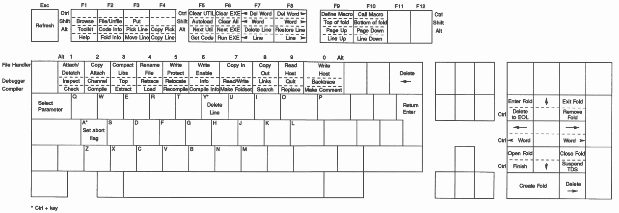
The TDS is an interactive system based on a full-screen text display on which operations are performed by actions at the keyboard. The ASCII keys are used for their normal purpose for entering text. Other keys have special meanings in the TDS, which do not in general correspond to the legends on the keytops.
The keyboard functions available are shown in Figure 1. The functions of the keys are fully described in the TDS User Manual.
Note that the notation of a name in a box (e.g. HELP) is used throughout this document to describe function keys.
The user is presented with a view of a collection of files and their contents. These files are kept between sessions in the DOS filing system. The display is hierarchical in the sense that there is a small number of root files containing a combination of text, other data and pointers to other files. At any time one or more files may be ’open’ in the sense that they have been transferred from disk into memory and their contents may be inspected on the screen.
A typical view showing system software, documentation and user software is shown below:
{{{F toplevel.top
...F CODE UTIL compilation utilities ...F CODE UTIL configuration utilities ...F CODE EXE Eprom Hex Program ...F COMMENT notes on the user program {{{ EXE user program ...F user program }}} ... PROGRAM a network program }}} |
The central data structuring concept is the fold which may either be closed to a single line on the screen or may (if it contains text) be opened up to expose its contents. A closed fold is displayed as a line starting with three dots ... and containing text known as the fold comment. An open fold is displayed as a pair of crease lines bracketting the lines which are contained in the fold. The top crease starts with {{{ and contains the fold comment; the bottom crease consists of }}} alone.
Another example:
some text
... a closed fold more text with a blank line below {{{ an opened fold text within the fold }}} |
Closed folds and text lines have equal status for such editing operations as COPY LINE and MOVE LINE, which may thereby be used for arbitrary manipulation of chunks of text or data.
To facilitate the visibility of the structure of the text, folds may be indented relative to the surrounding text. This indentation becomes compulsory when the text is occam source code, but is otherwise optional. One of the editor operations allows the user to ENTER a fold, so that it is seen without its enclosing environment.
Folds created directly by the editor will contain text. Other folds are created by compilers, and other tools, whose contents are binary code or data. Such folds cannot be opened and displayed by the editor.
A fold, whose immediate contents is a sequence of nested folds is called a fold bundle. A particular kind of fold bundle is used to bracket together a compilable program unit with the corresponding object code and descriptor information. Such a fold bundle is called a foldset if complete (in the sense that the code corresponds to the source), or a voidset if incomplete.
Folds of various types are distinguished internally by numbers called attributes. Identifying keywords may be found on a fold indicating its attributes. Folds may optionally be filed in the DOS filing system. (An implementation restriction disallows the filing of foldsets and voidsets, but requires their immediate contents to be filed).
It is important to realise that all operations in the development of occam programs are conducted from within the folding editor, and so there is no need to leave the system and return to DOS.
In addition to the general purpose function keys for editing, manipulation of folds, etc., there can at any one time be a set of utility functions which are obtainable by function key combinations including the digits 0-9. On the PC these function keys are combinations of the ALT shift key and a digit key.
Utility functions include the operations of compilation of programs, linking of compiled code, loading transputer networks, etc., etc.
Utilities are provided in packages of up to 10 at a time. A utility package may be thought of as an executable procedure with multiple entry points, any one of which may be called by means of a utility key. Folds containing packages of utilities are marked CODE UTIL. A utility is applied to a line (which is usually a fold) on the screen, by moving the cursor to that line and using the appropriate key sequence. The contents of the fold are used as inputs by the utility, which may in addition create new contents.
When a utility is applied to a fold, a parameter fold may pop up on the screen; this gives the user the chance to modify one or more of the parameters which determine the details of what the utility does. These parameters are all fully described in the User Manual and are not discussed in detail here.
The combination of utility function keys and parameter folds makes it unnecessary to support the alternative style of user interface based on command lines.
The UTILs provided with the TDS include all the compilation and other program development utilities and also a set of file utilities for transfer and conversion of files between the formats required by the TDS and those used by the underlying operating system (DOS).
Occam programs written by the user to be run within the TDS are coded as occam processes, and are run by causing the TDS to run them in parallel with its own support processes.
At any time there may be one current executable program which may be executed by means of the RUN CODE key. Folds containing executable procedures are marked EXE. Applying the COMPILE utility to such a fold generates within it a CODE EXE fold containing the compiled code of the executable program. This operation also changes the status of the fold bundle from voidset to foldset.
The parameter folds used by UTILs are kept in a special fold called the toolkit fold. This fold may be entered at any time by using the ENTER TOOLKIT key and it survives the end of a TDS session.
The toolkit fold may also be used to hold pointers to commonly used UTILs and EXEs and other frequently used information.
Up to a maximum of 32 UTILs and/or EXEs may be loaded at any one time. One of each may be made current at any time by using the NEXT UTIL or NEXT EXE key. The code of the currently loaded UTILs and EXEs share an area of memory on the B004 board called the user area. The remainder of the memory not occupied by the code of the TDS itself is used as workspace by the editor and its supporting fold manager, the current UTIL and the current EXE. The size of the user area is determined by the total amount of memory on the B004 board. The bigger the board the bigger the UTILs and EXEs that can be run.
The easiest way for beginners to write their first transputer programs is to create executable programs which will run within the TDS. The details of how to do this are set out in INMOS Technical note 3, ’Getting started with the TDS’, by David Cormie.
A program to be run within the TDS must be coded as an occam process optionally using the predefined names of channels between this process and its run time environment. Within the process arbitrary occam code may be written, including separate compilation bundles containing internal PROCs suitable for compilation independently of their environment.
Separate compilation bundles containing one or more procedure declarations are created by wrapping the source code in a bundle using the MAKE FOLDSET utility with parameter SC.
An executable occam program or EXE (not to be confused with a DOS .exe file), must be wrapped up in a bundle using the MAKE FOLDSET utility with parameter EXE. The program is then ready to be compiled and linked using the COMPILE utility to make an EXE foldset and to generate a CODE EXE fold within the foldset.
Applying GET CODE either to the CODE EXE fold or to the EXE bundle will load this program into the transputer board memory alongside the TDS where it is ready to be executed by RUN CODE.
When the TDS runs an executable program it is connected by channels to and from the TDS processes supporting the terminal and filing system. By using these channels a program is able to communicate data to and from these devices.
The filing system channels provide access to files which are part of the folded data structure visible through the editor. In particular access is provided to the filed folds in a fold bundle pointed to by the cursor at the time RUN CODE is pressed.
Communication using these channels must obey a set of protocols set out in the TDS reference manual. Examples of programs using these interfaces are included within the TDS product. By adapting these examples to the user’s requirements it is possible to write programs which perform input and output by calling procedures in the way that is familiar to most programmers using other high level programming languages. Procedures are provided for conversions in both directions between text and all the numeric types.
These procedures and others provided with the TDS may be managed by a library system which facilitates the sharing of code between different programs.
Executable occam programs are constrained by the memory area used by the TDS itself. Bigger programs can be written to run on the B004 without support from the TDS. A program which is designed to run without support from the TDS must take responsibility for all its own peripheral handling. Similar considerations apply to programs written for separate networks of transputers, whether on evaluation boards or in arbitrary user’s embedded systems.
If the network includes the transputer on the B004 running the TDS then the transputer on this board may communicate with a program running in the PC across the link connection.
If the network program is to be run with run-time support from the TDS, it will be necessary to write an interface program to run as an EXE within the TDS. This will talk across the link interface to the independently developed network program.
If the network includes an INMOS evaluation board with RS232 support then driving software for terminal handling will have been provided in the TDS or with the board. The user will have the option of accessing the terminal handler directly or may use an interface procedure provided within the TDS which supports an abstract terminal interface.
A transputer network program consists of a collection of separately compiled procedures, and an outermost occam process in the form of a PLACED PAR construct which describes the parallel execution of the code on each transputer in the configuration of transputers.
This construct is expressed in a subset of occam known as configuration language. The principal purpose of the configuration language is to describe the interconnection of processors by declaring channels, mapping them onto hardware INMOS link addresses, and to pass value and channel parameters to calls of procedures running on each processor. Regular arrays of transputers can be described economically by using replicators in configuration code.
The code to be run on any one processor must be written as a single procedure with parameters which are either values or channels. This procedure must be wrapped up in an SC separate compilation bundle by applying the MAKE FOLDSET utility with parameter SC to a filed fold containing its source text. This bundle is then compiled by applying the COMPILE utility to it.
A network program to be configured should be wrapped up in a PROGRAM fold bundle using the MAKE FOLDSET utility with parameter PROGRAM. If not already done, the separately compilable procedures (in SC bundles) may all be compiled by applying the COMPILE utility to the PROGRAM bundle; this operation will also compile the configuration code.
The EXTRACT utility may then be applied in turn to create a CODE PROGRAM fold within the bundle. This contains transputer code and routing information in a form that can subsequently be loaded down an INMOS link to the root processor of a network. The routing information enables the loader to direct code packets to all the transputers in a network.
The example below shows the configuration language for a simple 5 transputer network connected in a ring (an IMS B004 and an IMS B003 with the B004 as the root transputer used for loading):
{{{ PROGRAM B003test
{{{F B003test ... SC PROC HostProcess ... SC PROC TestProcess {{{ hardware link addresses VAL link0out IS 0: VAL link0in IS 4: VAL link1out IS 1: VAL link1in IS 5: VAL link2out IS 2: VAL link2in IS 6: VAL link3out IS 3: VAL link3in IS 7: }}} VAL linktab IS [[link0in,link2out], [link3in,link2out], [link3in,link2out], [link3in,link1out]]: -- table of hardware links VAL tab IS [[0,1],[1,2],[2,3],[3,4]]:-- table of link array indices [5]CHAN OF BYTE link: -- array of link channels PLACED PAR PROCESSOR -1 T4 -- on the B004 {{{ link channel placements PLACE link[0] AT link1out: PLACE link[4] AT link2in: }}} HostProcess (link[0], link[4]) -- uses links 1 and 2 PLACED PAR i = 0 FOR 4 -- on the B003 PROCESSOR i T4 VAL t.in IS tab[i,0]: VAL t.out IS tab[i,1]: {{{ link channel placements PLACE link[t.in] AT linktab[i,0]: PLACE link[t.out] AT linktab[i,1]: }}} TestProcess (link[t.in], link[t.out]) -- links from tab }}} }}} |
The LOAD NETWORK utility loads the code for a program running on a network down an INMOS link from the TDS B004.
The LOAD NETWORK utility may be applied to a CODE PROGRAM fold, or to a compiled and configured PROGRAM foldset from which the necessary code will be automatically extracted.
It is sometimes necessary to check how much code has been generated by a compilation, and how much workspace (data space) will be required to run it. It is a feature of the language that such figures can be determined at compile time. A display of such information for any separately compiled unit may be obtained using the COMPILATION INFO utility in the compiler utility package. If the unit is a PROGRAM it generates information in a fold labelled CONFIG INFO. This includes descriptions of the network connections implied by the configuration code and descriptions of where the code and workspace will be located.
Errors detected by the compiler or configurer result in an immediate display of the offending line in context on the screen. This makes it possible to correct the error immediately and to resubmit the corrected program for compilation.
There is no error recovery and compilation is not continued after an error. However only the current compilation is aborted and any separately compilable units (SCs) whose compilation has been completed will not require recompilation.
If the appropriate compile-time and load-time options have been selected a transputer program may stop at run-time for one of several reasons. Such reasons include array bounds violation, value range violation, arithmetic overflow, division by zero, etc.
On the occurrence of any such error it is possible to preserve the state of the root transputer in a dump file, and then, on restarting the TDS to run the DEBUGGER program. This enables the occam source line corresponding to the failure position to be displayed, and also enables the values of any variables in scope to be examined. A wide variety of additional features make it possible to trace the cause of most kinds of program failure both in EXEs and in PROGRAMS running on arbitrarily large networks.
There is a utility in the TDS which enables a transputer network program to be converted into a form which can be loaded from a DOS file to a transputer network including the TDS B004.
A program to be run in this way is responsible for all communication across the link at run time and must be supported by an appropriate server program running in the PC.
A transputer application may be designed for an ultimate system where it starts itself up from ROM. It is possible to put an arbitrary program into a ROM of appropriate size, which is capable of sending parts of itself to other transputers connected by links.
The transputer will boot from ROM or from any one of its links according to the state of its BOOTFROMROM pin on reset. The code which is booted may itself be a loader which will load further code, say through an RS232 port.
Below are described tools, provided in the TDS, which may be used to aid these tasks. These tools are written as EXEs and are used in the same way as programs written by the user.
An EPROM suitable for booting a transputer may include a table which defines the memory interface configuration. This is a feature of the transputer hardware which allows memory components with a wide variety of access requirements to be used. In the absence of such a table one of the default configurations in the transputer microcode will normally be used.
A tool is provided with the TDS to aid construction of such a memory configuration table.
A tool is provided with the TDS to aid the creation of loaders. This tool takes a program written to interpret a defined loading protocol for multi-transputer networks and adds to it the necessary transputer instructions to boot itself from a link.
A tool is provided which can make a file containing the code to be written into an EPROM for one of three kinds of system:
1) A program which constitutes a complete free-standing application.
2) A bootstrap loader such as that used in an evaluation board loaded from a host by way of an RS232 port or similar.
3) A loader and a network program to be distributed to an attached network of transputers.
In addition to the TDS system itself and the program development tools described above, the software includes significant collections of source code in occam. Some of these are also provided as compiled code in libraries.
These include:
| 1 | Conversion routines between numbers and text. |
| 2 | Mathematical function library for all transputer types. |
| 3 | Simple input output procedures. |
| 4 | Example programs using simple i/o procedures. |
| 5 | Some of the tools mentioned above which may need special adaptation. |
| 6 | The server programs and procedures for interfacing to them. |
| 7 | Procedures for terminal handling on transputer evaluation boards. |
Related software under development includes implementations of the Scientific languages, C, FORTRAN and Pascal. These implementations allow existing sequential programs in these languages to be compiled for the transputer, and allow parallel programs, using occam to express the concurrency, to have sequential components written in any of these languages.
Versions of the TDS for VAX/VMS and other host systems are also under development.