|
|
| The transputer implementation of occam _____________________________________________________________________ |
| David May and Roger Shepherd January 1988 |
VLSI technology allows a large number of identical devices to be manufactured cheaply. For this reason, it is attractive to implement an occam [1] program using a number of identical components, each programmed with the appropriate occam process. A transputer [2] is such a component.
A transputer is a single VLSI device with memory, processor and communications links for direct connection to other transputers. Concurrent systems can be constructed from a collection of transputers which operate concurrently and communicate through links.
The transputer can therefore be used as a building block for concurrent processing systems, with occam as the associated design formalism.
An important property of VLSI technology is that communication between devices is very much slower than communication on the same device. In a computer, almost every operation that the processor performs involves the use of memory. A transputer therefore includes both processor and memory in the same integrated circuit device.
In any system constructed from integrated circuit devices, much of the physical bulk arises from connections between devices. The size of the package for an integrated circuit is determined more by the number of connection pins than by the size of the device itself. In addition, connections between devices provided by paths on a circuit board consume a considerable amount of space.
The speed of communication between electronic devices is optimised by the use of one-directional signal wires, each connecting two devices. If many devices are connected by a shared bus, electrical problems of driving the bus require that the speed is reduced. Also, additional control logic and wiring is required to control sharing of the bus.
To provide maximum speed with minimal wiring, the transputer uses point-to-point serial communication links for direct connection to other transputers.
occam enables a system to be described as a collection of concurrent processes, which communicate with each other and with peripheral devices through channels. occam programs are built from three primitive processes:
| v := e | assign expression e to variable v |
| c ! e | output expression e to channel c |
| c ? v | input from channel c to variable v |
The primitive processes are combined to form constructs:
| SEQuential | components executed one after another |
| PARallel | components executed together |
| ALTernative | component first ready is executed |
A construct is itself a process, and may be used as a component of another construct.
Conventional sequential programs can be expressed with variables and assignments, combined in sequential constructs. IF and WHILE constructs are also provided.
Concurrent programs can be expressed with channels, inputs and outputs, which are combined in parallel and alternative constructs.
Each occam channel provides a communication path between two concurrent processes. Communication is synchronised and takes place when both the inputting process and the outputting process are ready. The data to be output is then copied from the outputting process to the inputting process, and both processes continue.
An alternative process may be ready for input from any one of a number of channels. In this case, the input is taken from the channel which is first used for output by another process.
A transputer system consists of a number of interconnected transputers, each executing an occam process and communicating with other transputers. As a process executed by a transputer may itself consist of a number of concurrent processes the transputer has to support the occam programming model internally. Within a transputer concurrent processing is implemented by sharing the processor time between the concurrent processes.
The most effective implementation of simple programs by a programmable computer is provided by a sequential processor. Consequently, the transputer processor is fairly conventional, except that additional hardware and microcode support the occam model of concurrent processing.
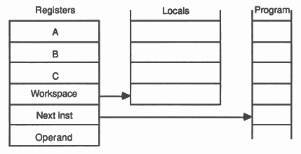
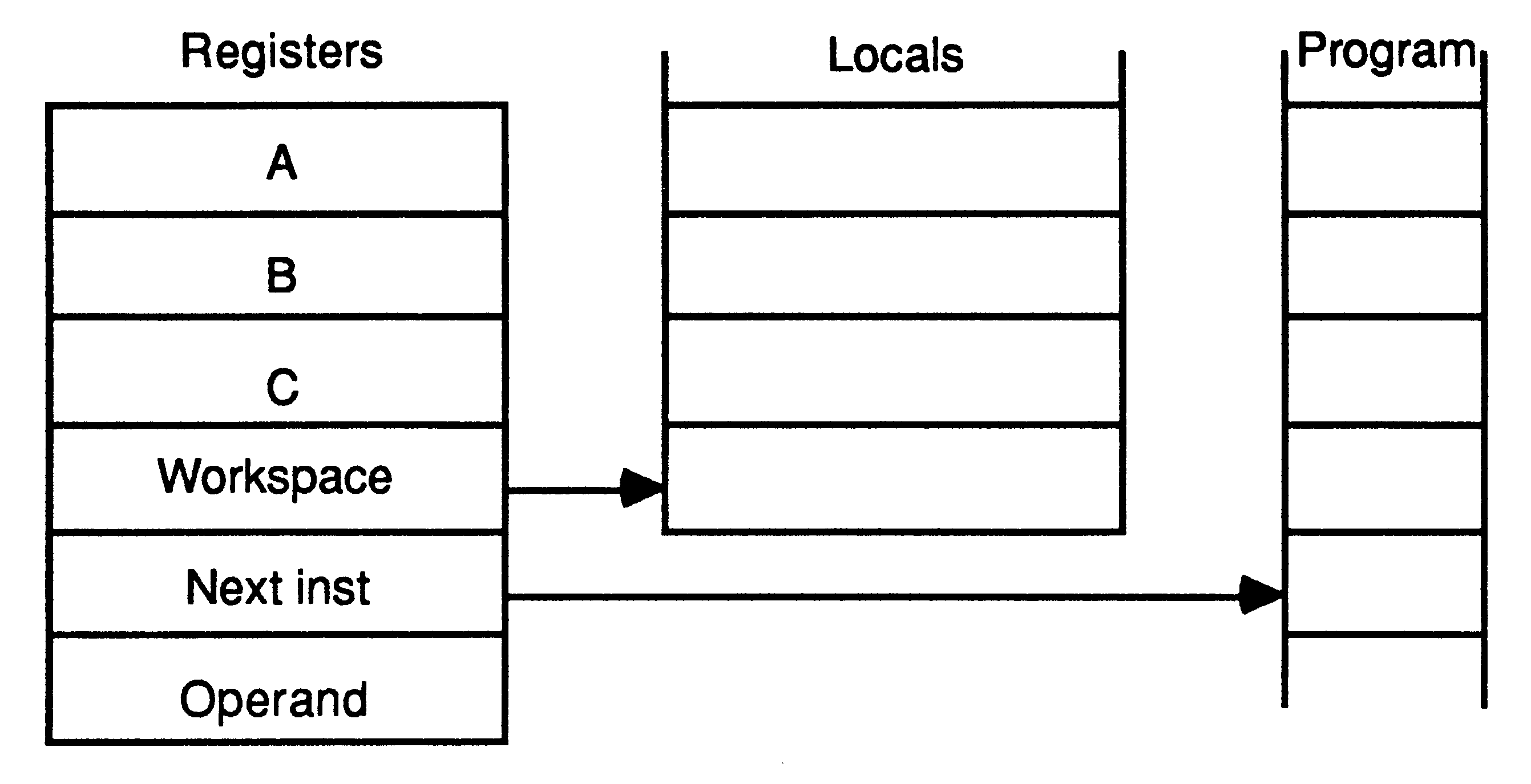
The design of the transputer processor exploits the availability of fast on-chip memory by having only a small number of registers; six registers are used in the execution of a sequential process. The small number of registers, together with the simplicity of the instruction set enables the processor to have relatively simple (and fast) data-paths and control logic.
The six registers are:
|
|
Expressions are evaluated on the evaluation stack, and instructions refer to the stack implicitly. For example, the ’add’ instruction adds the top two values in the stack and places the result on the top of the stack. The use of a stack removes the need for instructions to respecify the location of their operands. Statistics gathered from a large number of programs show that three registers provide an effective balance between code compactness and implementation complexity.
No hardware mechanism is provided to detect that more than three values have been loaded onto the stack. It is easy for the compiler to ensure that this never happens.
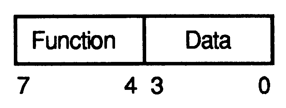
It was a design decision that the transputer should be programmed in a high-level language. The instruction set has, therefore, been designed for simple and efficient compilation. It contains a relatively small number of instructions, all with the same format, chosen to give a compact representation of the operations most frequently occuring in programs. The instruction set is independant of the processor wordlength, allowing the same microcode to be used for transputers with different wordlengths. Each instruction consists of a single byte divided into two 4 bit parts. The four most significant bits of the byte are a function code, and the four least significant bits are a data value.
|
|
The representation provides for sixteen functions, each with a data value ranging from 0 to 15. Thirteen of these are used to encode the most important functions performed by any computer. These include:
load constant add constant
load local store local load local pointer load non-local store non-local jump conditional jump call |
The most common operations in a program are the loading of small literal values, and the loading and storing of one of a small number of variables. The ’load constant’ instruction enables values between 0 and 15 to be loaded with a single byte instruction. The ’load local’ and ’store local’ instructions access locations in memory relative to the workspace pointer. The first 16 locations can be accessed using a single byte instruction.
The ’load non-local’ and ’store non-local’ instructions behave similarly, except that they access locations in memory relative to the A register. Compact sequences of these instructions allow efficient access to data structures, and provide for simple implementations of the static links or displays used in the implementation of block structured programming languages such as occam.
Two more of the function codes are used to allow the operand of any instruction to be extended in length. These are:
prefix
negative prefix |
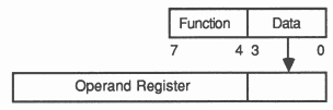
All instructions are executed by loading the four data bits into the least significant four bits of the operand register, which is then used as the the instruction’s operand. All instructions except the prefix instructions end by clearing the operand register, ready for the next instruction.
|
|
The ’prefix’ instruction loads its four data bits into the operand register, and then shifts the operand register up four places. The ’negative prefix’ instruction is similar, except that it complements the operand register before shifting it up. Consequently operands can be extended to any length up to the length of the operand register by a sequence of prefix instructions. In particular, operands in the range -256 to 255 can be represented using one prefix instruction.
The use of prefix instructions has certain beneficial consequences. Firstly, they are decoded and executed in the same way as every other instruction, which simplifies and speeds instruction decoding. Secondly, they simplify language compilation, by providing a completely uniform way of allowing any instruction to take an operand of any size. Thirdly, they allow operands to be represented in a form independent of the processor wordlength.
The remaining function code, ’operate’, causes its operand to be interpreted as an operation on the values held in the evaluation stack. This allows up to 16 such operations to be encoded in a single byte instruction. However, the prefix instructions can be used to extend the operand of an ’operate’ instruction just like any other. The instruction representation therefore provides for an indefinite number of operations.
The encoding of the indirect functions is chosen so that the most frequently occuring operations are represented without the use of a prefix instruction. These include arithmetic, logical and comparison operations such as
add
exclusive or greater than |
Less frequently occuring operations have encodings which require a single prefix operation (the transputer instruction set is not large enough to require more than 512 operations to be encoded!).
Evaluation of expressions may require the use of temporary variables in the process workspace, but the number of these can be minimised by careful choice of the evaluation order.
Let depth(e) be the number of stack locations needed for the evaluation of expression e, defined by:
depth(constant) = 1
depth(variable) = 1 depth(e1 op e2) = IF depth(e1) > depth(e2) THEN depth(e1) ELSE IF depth(e1) < depth(e2) THEN depth(e2) ELSE depth(e1) + 1 |
Let commutes(operator) be true if the operator commutes, false otherwise.
Let e1 and e2 be expressions. The expression of (e1 op e2) is compiled for the 3 register stack by:
compile(e1 op e2) =
IF depth(e2) > depth(e1) THEN IF depth(el) > 2 THEN (compile(e2); store temp; compile(e1); load temp; op) ELSE IF commutes(op) THEN (compile(e2); compile(e1); op) ELSE (compile(e2); compile(e1); reverse; op) ELSE IF depth(e2) < 3 THEN (compile(e1); compile(e2); op) ELSE (compile(e2); store temp; compile(e1); load temp; op) |
where (I1;I2; ... In) represents a sequence of instructions.
Measurements show that about 80% of executed instructions are encoded in a single byte (i.e. without the use of prefix instructions). Many of these instructions, such as ’load constant’ and ’add’ require just one processor cycle.
The instruction representation gives a more compact representation of high level language programs than more conventional instruction sets. Since a program requires less store to represent it, less of the memory bandwidth is taken up with fetching instructions. Furthermore, as memory is word accessed the processor will receive several instructions for every fetch.
Short instructions also improve the effectiveness of instruction prefetch, which in turn improves processor performance. There is an extra word of prefetch buffer so that the processor rarely has to wait for an instruction fetch before proceeding. Since the buffer is short, there is little time penalty when a jump instruction causes the buffer contents to be discarded.
The processor provides efficient support for the occam model of concurrency and communication. It has a microcoded scheduler which enables any number of concurrent processes to be executed together, sharing the processor time. This removes the need for a software kernel. The processor does not need to support the dynamic allocation of storage as the occam compiler is able to perform the allocation of space to concurrent processes.
At any time, a concurrent process may be
| active | - | being executed |
| - | on a list waiting to be executed | |
| inactive | - | ready to input |
| - | ready to output | |
| - | waiting until a specified time | |
The scheduler operates in such a way that inactive processes do not consume any processor time.
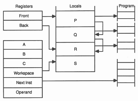
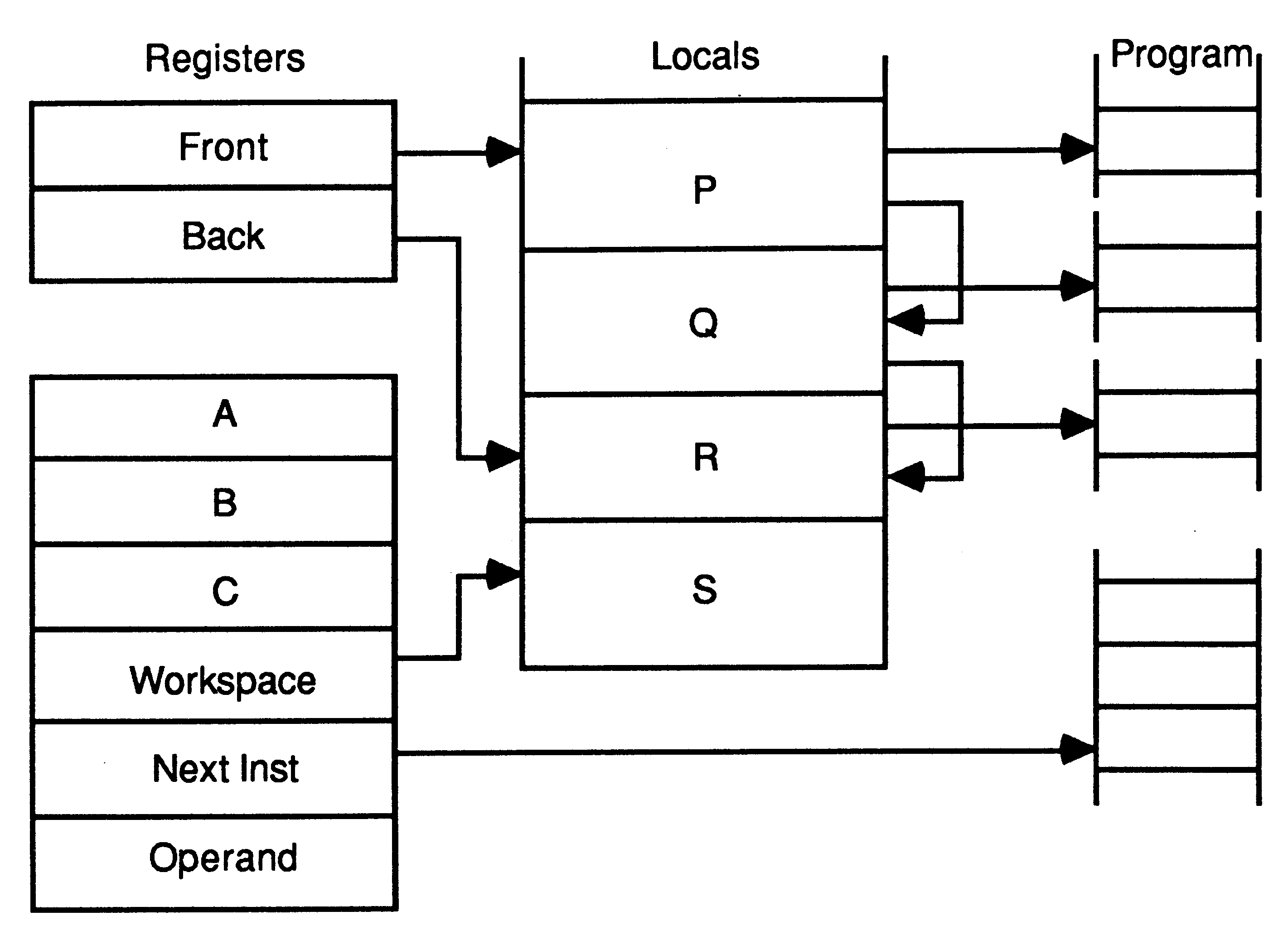
The active processes waiting to be executed are held on a list. This is a linked list of process workspaces, implemented using two registers, one of which points to the first process on the list, the other to the last.
In this illustration, S is executing, and P, Q and R are active, awaiting execution:
|
|
A process is executed until it is unable to proceed because it is waiting to input or output, or waiting for the timer. Whenever a process is unable to proceed, its instruction pointer is saved in its workspace and the next process is taken from the list. Actual process switch times are very small as little state needs to be saved; it is not necessary to save the evaluation stack on rescheduling.
The processor provides a number of special operations to support the process model. These include
start process
end process |
When a parallel construct is executed, ’start process’ instructions are used to create the necessary concurrent processes. A ’start process’ instruction creates a new process by adding a new workspace to the end of the scheduling list, enabling the new concurrent process to be executed together with the ones already being executed. The correct termination of a parallel construct is assured by use of the ’end process’ instruction. This uses a workspace location as a counter of the components of the parallel construct which have still to terminate. The counter is initialised to the number of components before the processes are ’started’. Each component ends with an ’end process’ instruction which decrements and tests the counter. For all but the last component, the counter is non zero and the component is descheduled. For the last component, the counter is zero and the component continues.
Communication between processes is achieved by means of channels. occam communication is point-to-point, synchronised and unbuffered. As a result, a channel needs no process queue, no message queue and no message buffer.
A channel between two processes executing on the same transputer is implemented by a single word in memory; a channel between processes executing on different transputers is implemented by point-to-point links. The processor provides a number of operations to support message passing, the most important being
input message
output message |
The ’input message’ and ’output message’ instructions use the address of the channel to determine whether the channel is internal or external. This means that the same instruction sequence can be used for both hard and soft channels, allowing a process to be written and compiled without knowledge of where its channels are connected.
As in the occam model, communication takes place when both the inputting and outputting processes are ready. Consequently, the process which first becomes ready must wait until the second one is also ready.
A process performs an input or output by loading the evaluation stack with a pointer to a message, the address of a channel, and a count of the number of bytes to be transferred, and then executing an ’input message’ or an ’output message’ instruction.
At any time, an internal channel (a single word in memory) either holds the identity of a process, or holds the special value ’empty’. The channel is initialised to ’empty’ before it is used.
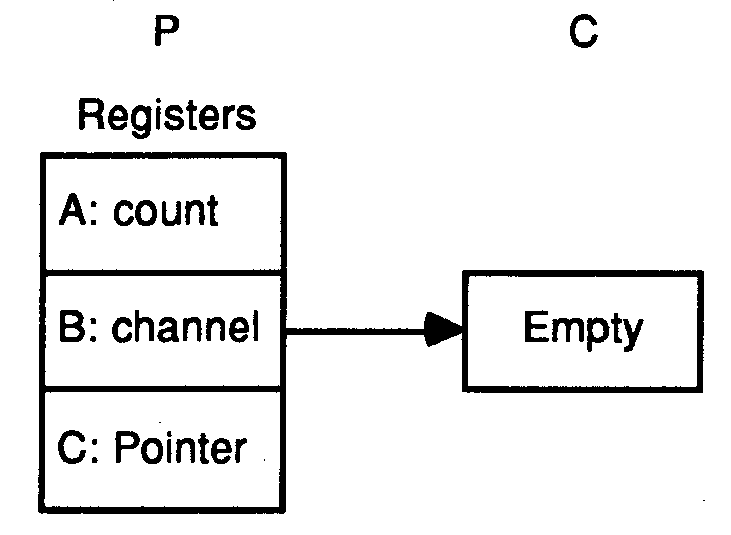
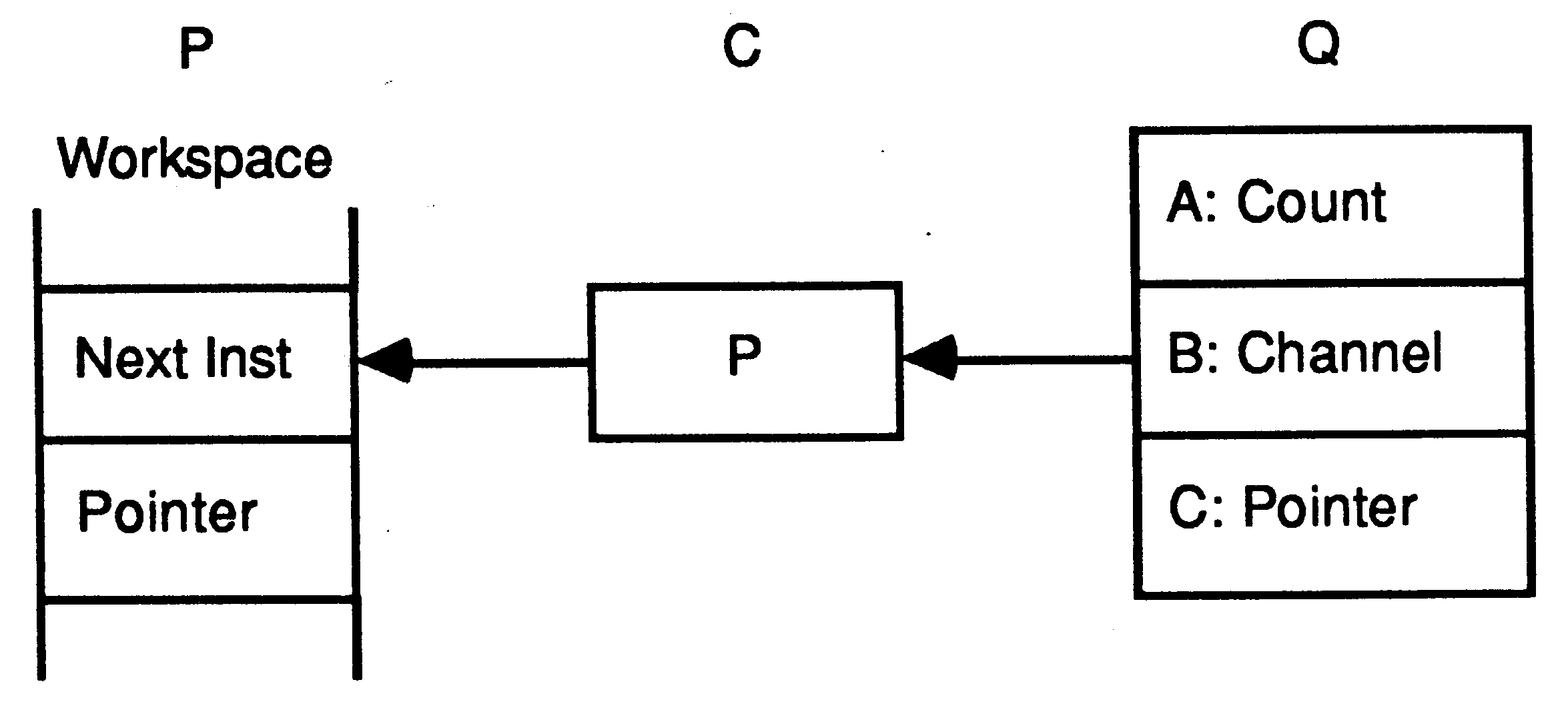
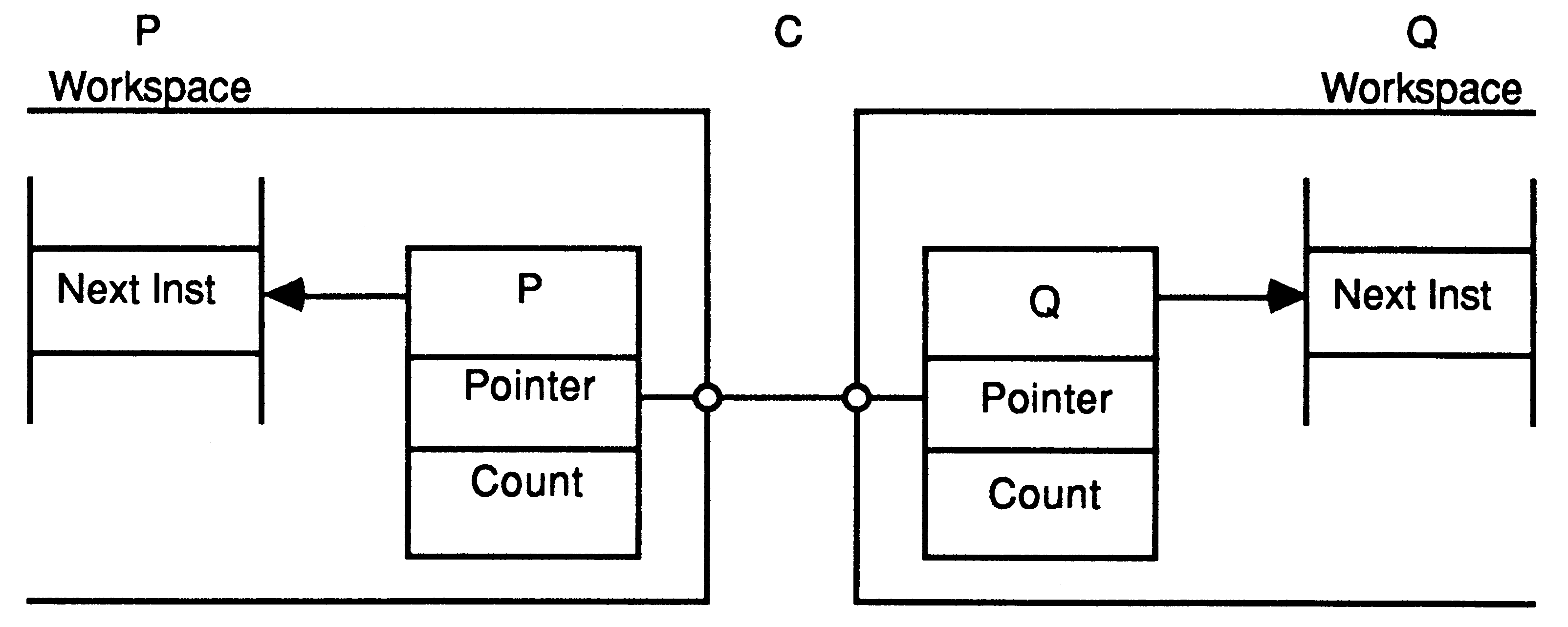
When a message is passed using the channel, the identity of the first process to become ready is stored in the channel, and the processor starts to execute the next process from the scheduling list. When the second process to use the channel becomes ready, the message is copied, the waiting process is added to the scheduling list, and the channel reset to its initial state. It does not matter whether the inputting or the outputting process becomes ready first. In the following illustration, a process P is about to execute an output instruction on an ’empty’ channel C. The evaluation stack holds a pointer to a message, the address of channel C, and a count of the number of bytes in the message.
|
|
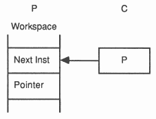
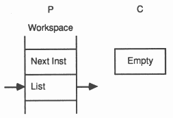
After executing the output instruction, the channel C holds the address of the workspace of P, and the address of the message to be transferred is stored in the workspace of P. P is descheduled, and the process starts to execute the next process from the scheduling list.
|
|
The channel C and the process P remain in this state until a second process, Q executes an input instruction on the channel.
|
|
The message is copied, the waiting process P is added to the scheduling list, and the channel C is reset to its initial ’empty’ state.
|
|
When a message is passed via an external channel the processor delegates to an autonomous link interface the job of transferring the message and deschedules the process. When the message has been transferred the link interface causes the processor to reschedule the waiting process. This allows the processor to continue the execution of other processes whilst the external message transfer is taking place.
Each link interface uses three registers:
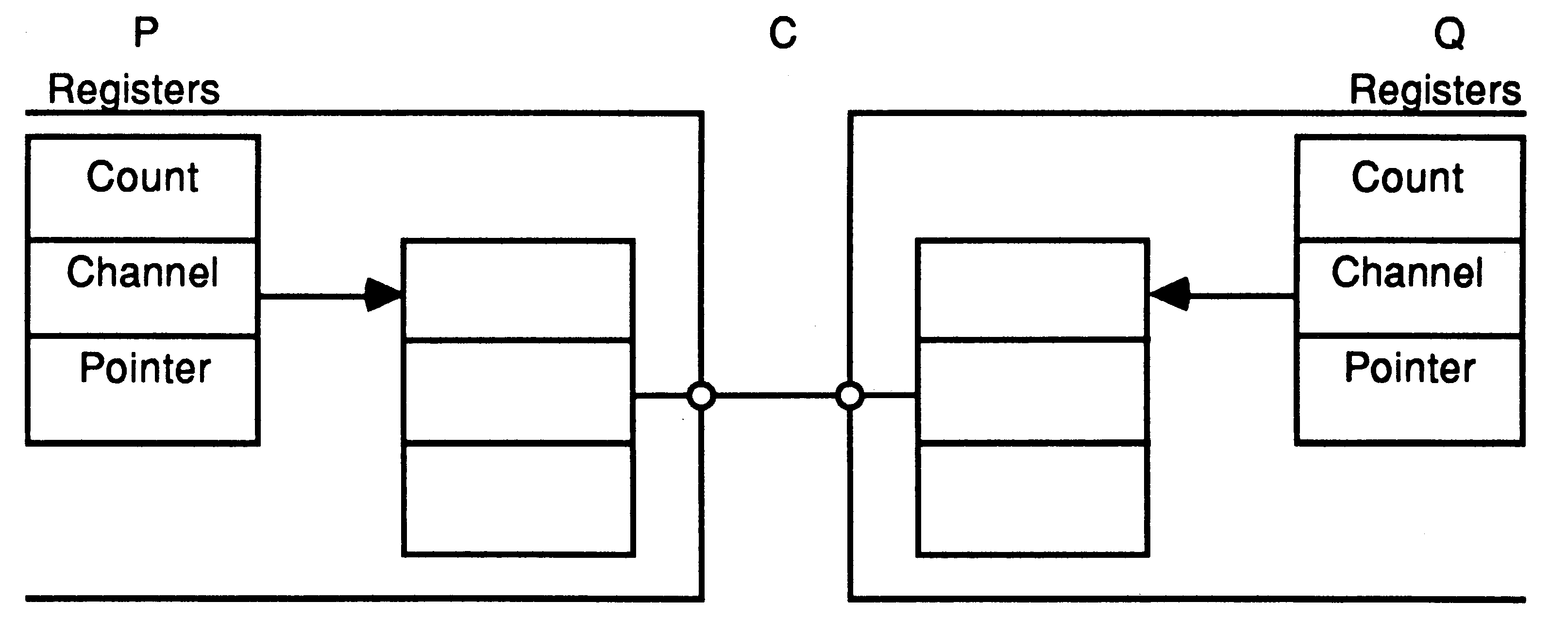
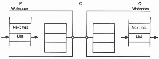
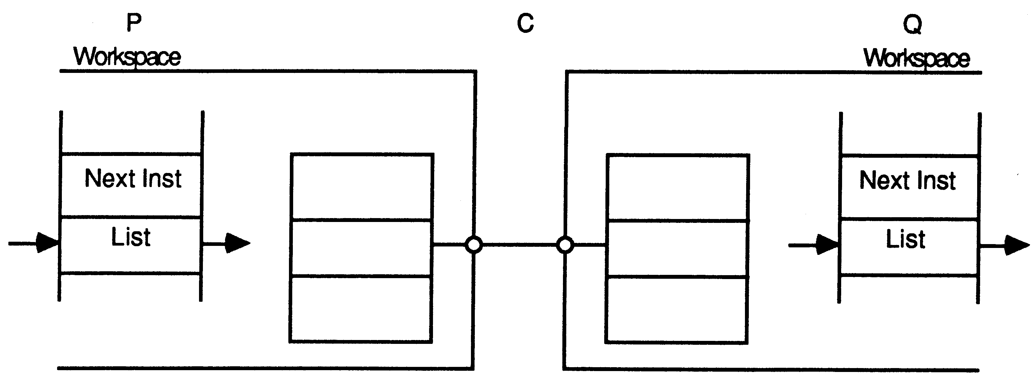
In the following illustration, processes P and Q executed by different transputers communicate using a channel C implemented by a link connecting two transputers. P outputs, and Q inputs.
|
|
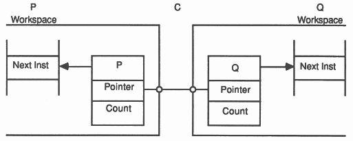
When P executes its output instruction, the registers in the link interface of the transputer executing P are initialised, and P is descheduled. Similarly, when Q executes its input instruction, the registers in the link interface of the process executing Q are initialised, and Q is descheduled.
|
|
The message is now copied through the link, after which the workspaces of P and Q are returned to the corresponding scheduling lists. The protocol used on P and Q ensures that it does not matter which of P and Q first becomes ready.
|
|
The transputer has a clock which ’ticks’ every microsecond. The current value of the processor clock can be read by executing a ’Read timer’ instruction.
A process can arrange to perform a ‘timer input’, in which case it will become ready to execute after a specified time has been reached.
The timer input instruction requires a time to be specified. If this time is in the ’past’ (i.e. ClockReg AFTER SpecifiedTime) then the instruction has no effect. If the time is in the ‘future’ (i.e. SpecifiedTime AFTER Clockreg or SpecifiedTime = ClockReg) then the process is descheduled. When the specified time is reached the process is scheduled again.
The occam alternative construct enables a process to wait for input from any one of a number of channels, or until a specific time occurs. This requires special instructions, as the normal ’input’ instruction deschedules a process until a specific channel becomes ready, or until a specific time is reached. The instructions used are:
enable channel enable timer
disable channel disable timer alternative wait |
The alternative is implemented by ’enabling’ the channel input or timer input specified in each of its components. The ’alternative wait’ is then used to deschedule the process if none of the channel or timer inputs is ready; the process will be re-scheduled when any one of them becomes ready. The channel and timer inputs are then ’disabled’. The ’disable’ instructions are also designed to select the component of the alternative to be executed; the first component found to be ready is executed.
To provide synchronised communication, each message must be acknowledged. Consequently, a link requires at least one signal wire in each direction.
A link between two transputers is implemented by connecting a link interface on one transputer to a link interface on the other transputer by two one-directional signal lines, along which data is transmitted serially.
The two signal wires of the link can be used to provide two occam channels, one in each direction. This requires a simple protocol. Each signal line carries data and control information.
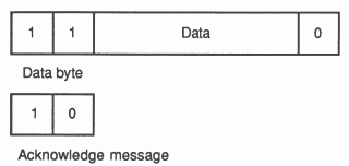
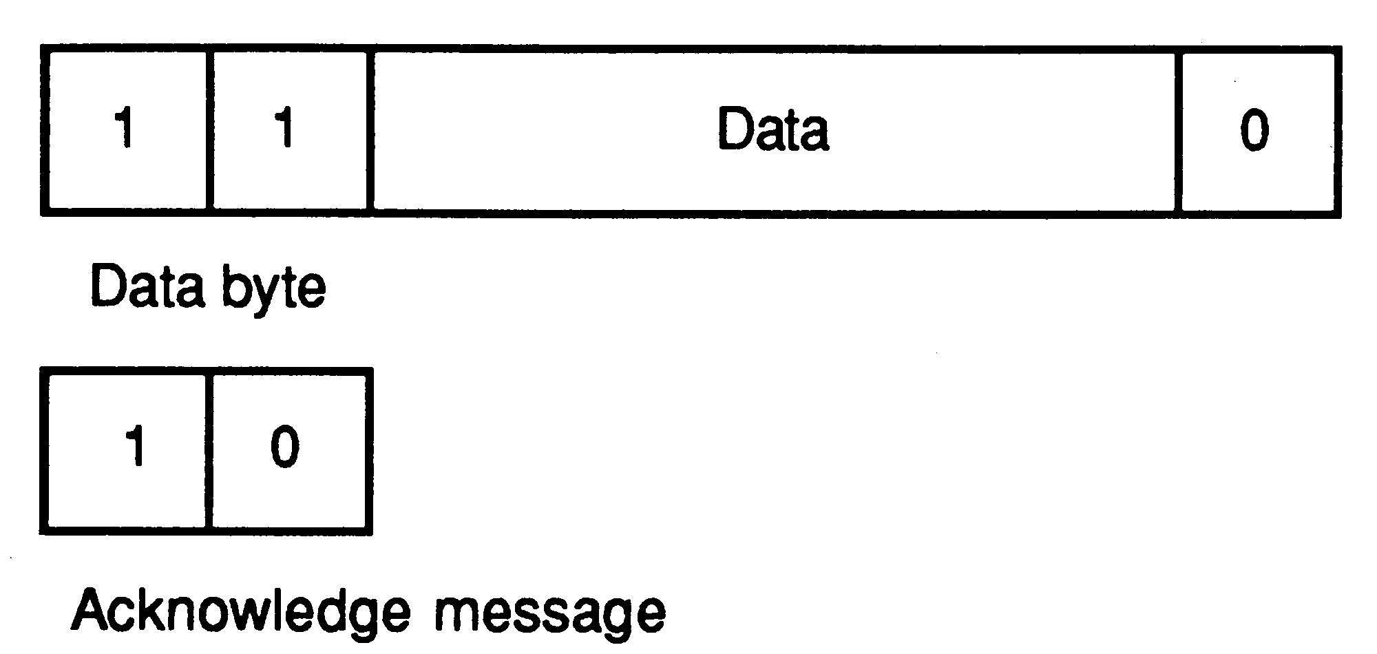
The link protocol provides the synchronised communication of occam. The use of a protocol providing for the transmission of an arbitrary sequence of bytes allows transputers of different wordlength to be connected. Each message is transmitted as a sequence of single byte communications, requiring only the presence of a single byte buffer in the receiving transputer to ensure that no information is lost. Each byte is transmitted as a start bit followed by a one bit followed by the eight data bits followed by a stop bit. After transmitting a data byte, the sender waits until an acknowledge is received; this consists of a start bit followed by a zero bit. The acknowledge signifies both that a process was able to receive the acknowledged byte, and that the receiving link is able to receive another byte. The sending link reschedules the sending process only after the acknowledge for the final byte of the message has been received.
|
|
Data bytes and acknowledges are multiplexed down each signal line. An acknowledge is transmitted as soon as reception of a data byte starts (if there is room to buffer another one). Consequently transmission may be continuous, with no delays between data bytes.
Experience with occam has shown that many applications naturally decompose into a large number of fairly simple processes. Once an application has been described in occam, a variety of implementations are possible. In particular, the use of occam together with the transputer enables the designer to exploit the performance and economics of VLSI technology. The concurrent processing features of occam can be efficiently implemented by a small, simple and fast processor.
The transputer therefore has two important uses. Firstly it provides a new system ’building block’ which enables occam to be used as a design formalism. In this role, occam serves both as a system description language and a programming language. Secondly, occam and the transputer can be used for prototyping highly concurrent systems in which the individual processes are ultimately intended to be implemented by dedicated hardware.