|
|
| Some issues in
scientific-language application porting and farming using transputers _____________________________________________________________________ |
| Andy Hamilton Central Applications Group INMOS Bristol July 1989 |
Until recently, cost-effective parallel processing was not available to commerce and industry. Software was designed and implemented sequentially. Performance upgrades were achieved by using faster hardware and dirty tricks. Ultimately, though, the Von Neumann bottleneck limits the performance of such a system.
The INMOS transputer [1] avails new opportunities in performance, flexibility, and cost-effectiveness. Software can now be written to execute concurrently over a transputer network of arbitrary size, depending on the required performance.
INMOS developed a programming language called occam [2] to express parallel requirements. Occam is the preferred programming language for the transputer. However, to protect the existing software investments of applications not written in occam, INMOS provide a set of so-called scientific-language compilers for the languages C, Pascal, and FORTRAN. Ada is under development. These compilers allow applications written before the advent of the transputer to take advantage of the performance and expandability of the transputer architecture.
This document demonstrates how easy it is to use existing application software with INMOS transputers. The techniques, which are all incremental and progressively testable, do not require the application to be rewritten. Each intermediate stage produces useful operable software, allowing any amount of time and effort expended to result in an inherently better product. By observing the problems associated with porting and paralleling existing applications, a framework and guidelines for writing future non-occam applications becomes apparent.
In performing a port to transputers, there is often very little occam to be written. Much of this occam falls into standard frameworks, which are available from INMOS. This helps to remove some of the ’tedious’ supervisory aspects.
Since C developers are expected to represent the largest body of people undertaking application porting, a lot of this document will refer to C terminology and examples, but without any loss of generality. The INMOS scientific-language compilers are all handled and used the same way, as far as a mixed language application is concerned. The main software tools required to implement the techniques shown are contained within the INMOS occam-2 toolsets.
This document does not fully explore worked solutions, but rather provides examples and offers suggestions for programmers to work with. The code fragments written in occam should be readily understandable, but it is not important for the reader to understand the occam in order to understand the examples and concepts.
Three dots ... will be used to represent areas of concealed source text in both occam and non-occam examples. It will be assumed that any applications referred to are not written in occam.
The assistance of Phil Atkin, Jamie Packer, Steve Ghee, David Shepherd, Sara Xavier, and Malcolm Boffey is gratefully acknowledged.
Before discussing the porting of an application to a transputer system, there are a few preliminary details that are appropriately explained at this juncture.
The INMOS transputer consists of a high-performance processor, on-chip RAM, and inter-processor links, all on a single chip of silicon. The on-chip RAM is very fast (40ns access time on the 25 MHz part), and allows fast data access and fast code execution in comparison to off-chip performance (the INMOS development tools allow the user’s application to make use of the on-chip RAM [3]). The inter-processor links are autonomous DMA engines, and permit any number of transputers to be connected together in arbitrary networks, allowing extra processing power to be injected into a system very easily. The external memory interface allows linear access to a total memory space of 4 gigabytes on the 32-bit devices.
The transputer family includes 16-bit and 32-bit architecture processors. For further information on the transputer family, the reader is directed to [1]. For comparative guidelines on the most suitable transputer / board products for your application, refer to [4].
Transputers are hardware processors. Transputer processors execute software processes. Any number of processes can be executed on a single transputer processor at the same time. The architecture and instructions of the transputer family have been designed to efficiently support high level languages. Transputers can be programmed in conventional sequential languages such as C, Pascal, and FORTRAN.
The programming model for transputers is defined by occam. Occam offers best support for utilizing the concurrency and communication facilities offered by transputers. Using occam, a system framework can be described in terms of a collection of concurrent processes which communicate with each other and with the outside world. These processes can be written in any language. Processes not written in occam can be encapsulated in a standard and simple occam framework which makes them appear as an equivalent occam processes (the EOP, [3]). This allows them to be used without restriction in mufti-process environment.
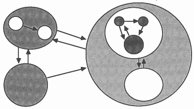
Processes are connected together using synchronized, un-buffered, point-to-point, uni-directional communication channels. An example of this is shown in Figure 1, where each circle represents a process, and each arrow represents a communications channel. Each process may be written in a different language.
Processes can be mapped onto transputers in an arbitrary configuration, which is independent of the processes themselves. It is not necessary to recompile any of the processes in order to change the way they are mapped onto the available hardware.
In the context of application porting, part or all of the application will be compiled and made to appear as an occam process in the system.
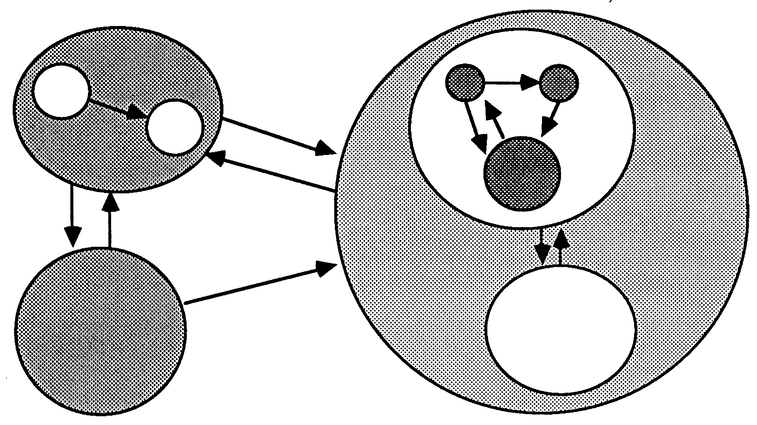
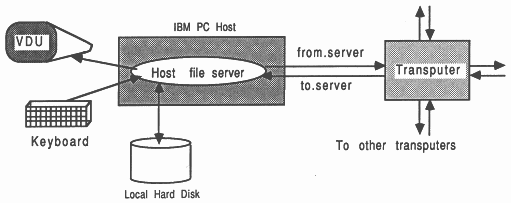
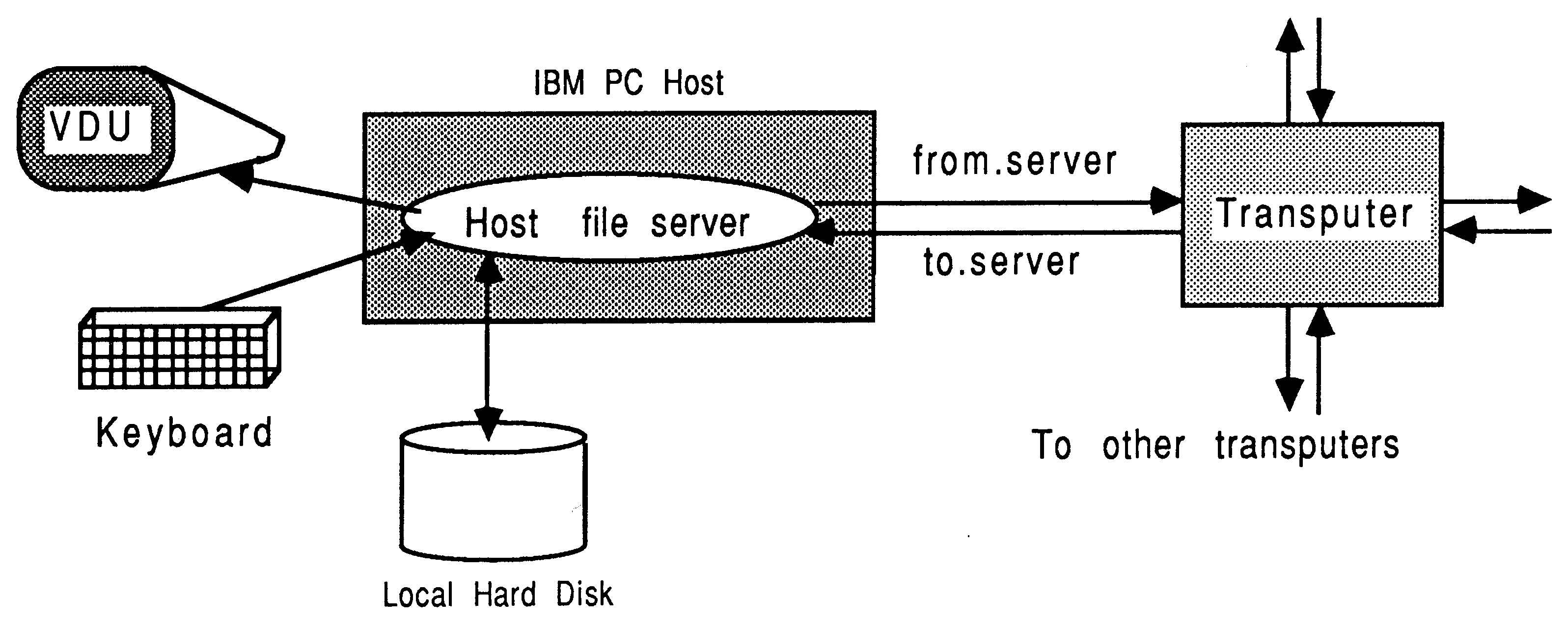
In the development environment, the transputer is normally employed as an addition to an existing computer, referred to as the host. Through the host, the transputer application can receive the services of a file store, a screen, and a keyboard. Presently, the host computer can be an IBM PC or compatible, a NEC PC, a DEC MicroVAX II, or a Sun-3: One example of this arrangement is shown in Figure 2. In all cases, the development tools execute on the transputer connected to the host. In addition, the VAX- and Sun-hosted systems offer tools and utilities which execute directly on that host. For a more thorough guide to product availability, please refer to [4].
The transputer communicates with the host along a single INMOS link. A program, called a server, executes on the host at the same time as the program on the transputer network is run. All communications between the application running on the transputer and the host services (like screen, keyboard, and filing resources) take the form of messages. Software written with the INMOS occam toolsets and scientific-language compilers, to use the standard INMOS servers, assume master status in a master / slave relationship between the transputer and the host. In this situation, messages are always initiated by the transputer system.
The root transputer in a network is the transputer connecting to the host bus via the link adapter. Any other transputers in the network are connected together using INMOS links, to the root transputer. A transputer network can contain any size and mix of transputer types.
The relationship between the transputer and the host during software development does not impose restrictions on the way the transputer is employed in the target environment.
Before proceeding further, consider why one may wish to port all or part of an existing application onto a transputer system.
OK, so you just can’t wait to get started. What do you hope to achieve with your port? Let’s look at a few categories of porting open to you:
Depending on the requirements of the port, the time available, and the characteristics of the application, the following list outlines the categories of application porting:
This involves porting all the application onto a single transputer, with no attempt at parallelization of the code. The standard services offered by the host server are assumed. This is the fastest to implement, but is the most restricted in terms of suitable applications.
For various reasons, it may not be desirable or suitable for the whole application to operate on a transputer system. In this case, a transputer system can be implemented to accommodate part of the application; a so-called part port.
This involves attempting to inject some computation power exactly where it’s needed in an application. The transputer software is fragmented into a small number of modules that execute concurrently, and these can then be distributed across multiple transputers using various application-specific and general-purpose techniques. Examples of this, discussed later, would be to introduce algorithmic, geometric, or farming parallelism.
Each category of porting offers a phased, progressive implementation. Each step builds on the workings of a previous, operational stage. For example, the transputer software would be initially ported without introducing parallelism, to execute on a single transputer. Then, it would be fragmented into a small number of modules, using a stub technique to minimize disarray in the source environment. Then, a multiplicity of transputers would be introduced. Each stage results in a useful working product, building incrementally on a working platform.
The remainder of the document discusses these categories of application porting, and the incremental tuning stages, in more detail. But first, let’s survey what tools exist to help.
INMOS provide a range of scientific-language development systems for C, Pascal, and FORTRAN. All these support the 32-bit transputer family. In conjunction with Alsys, an Ada environment is being developed, which can additionally target to the 16-bit transputers. On there own, the vanilla scientific-language development systems permit a single transputer, single process application to be constructed.
To build a multiple processor system, one is advised to use an INMOS occam-2 toolset, in conjunction with the appropriate scientific-language compiler. The toolsets are available for PC, Sun-3, and VAX environments, and offer debugging facilities. The examples in this document will refer to tools for the PC environment, and in particular, the D705B occam toolset. Access to [3] is useful. Remember though, that for example C software compiled using the PC development system can be integrated with other parts of an application on a VAX platform, with the ultimate intention of hosting it on a Sun-3 etc. This trans-platformal portability overcomes limitations of availability of development tools across the spectrum of platforms.
There are, of course, other development systems to select from. The INMOS Parallel C and Parallel FORTRAN systems permit multiple process systems to be accommodated, without requiring any occam to ”connect” the modules together.
Many third parry development systems exist. In addition to the C, Pascal, and FORTRAN compilers, there are third party offerings for Lisp, Prolog, Modula-2, Strand, and BASIC. Some tools are aimed specifically at one language on one platform, offering an integrated range of compilers, profilers, and debuggers, such as Meiko’s CStools for Sun-3 C applications, or Parasoft’s Express. In addition, some standard libraries are available for scientific and engineering applications (such as NAG, FLOLIB etc). Caplin Cybernetics offer a range of MicroVAX development tools to allow communication between the VAX and a transputer application (the Caplin VAX/CSP libraries). A number of transputer operating systems are also available, such as HELIOS, transIDRIS, and Hobbes.
Reference to [18] will show a selection of development products available from third party developers. Make sure you get your copy. INMOS would be pleased to advise individual customers on any aspects of software development tool applicability.
This chapter considers the simplest porting situation for an application. The application is to be lifted from an arbitrary computer system, and executed on a single transputer connected to a supported host platform.
Compliance with the goal of altering the application as little as possible requires that the entire application is executed on a single transputer. This is because the programmer can overlook the additional overheads of decomposing the application into a distributed interacting parallel system, and can use the standard INMOS occam supporting software.
The goal is to modify the application as little as possible, while achieving significant performance increase.
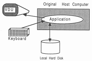
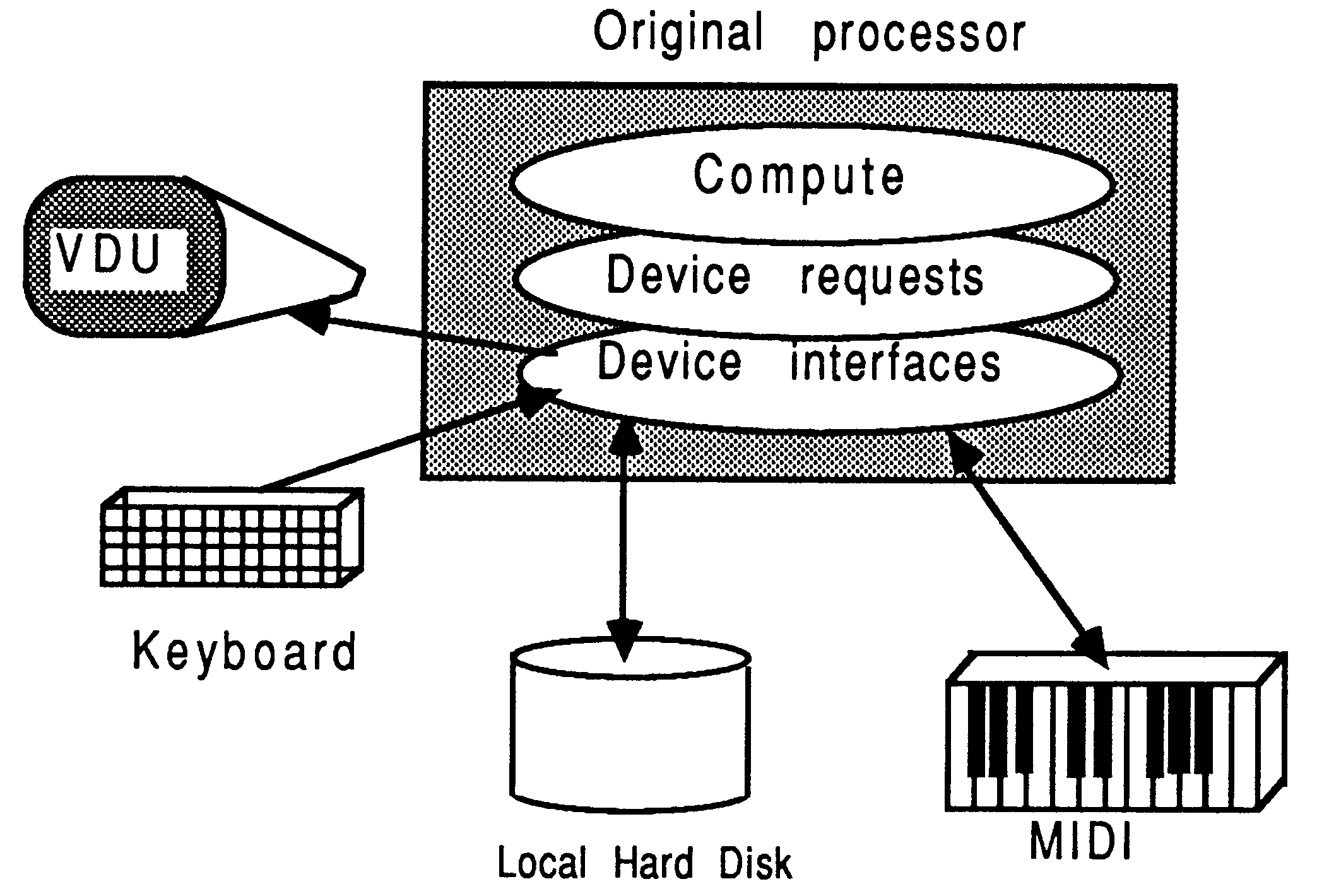
Before the porting to transputers, the application looks like Figure 3. No assumptions are made about the nature and capabilities of the original compute engine, except that the application uses only the following facilities through standard function calls to the language’s run-time library:
It is significant that the Figure does not show the application as having access to any special host-dependent interfacing features, and the original host’s identity is not important.
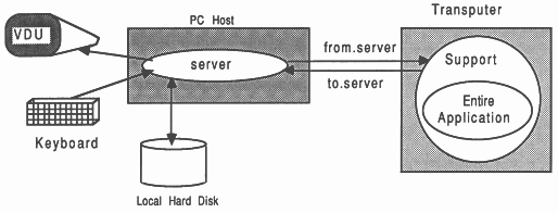
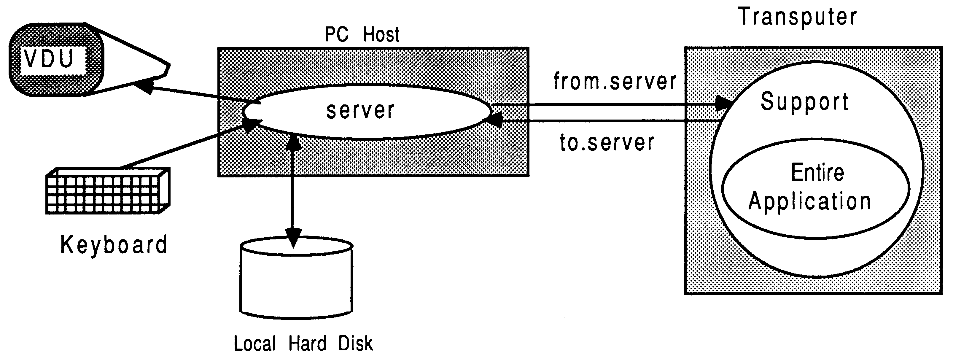
The ported application is shown in Figure 4. It is shown in the context of a PC host. This can be thought of as a flat port, in the sense that no articulation or re-arrangement of the program structure is performed.
The host system, shown as an IBM PC, runs a simple program called a server which ensures that the access requirements of the application in terms of keyboard, screen, and filing, are fully satisfied. The standard INMOS server supplied with the scientific-language development systems and the D705A occam toolset is called AFserver. This server is not recommended for use with application ports.
The occam-2 toolsets use a different server called iserver. it must be stressed that all new software tools / applications should be written to use the INMOS iserver where-ever possible. This server is available on a growing number of host platforms (such as VAX and Sun-3) and environments (such as HELIOS). It’s adoption brings immediate binary-level platform portability for the software concerned.
A small amount of software support is required on the transputer, shown in the Figure. In this specific situation of minimal modification to the application, the support is concealed from the programmer and is supplied by INMOS with the development systems.
For the fastest and simplest route to implement an application on transputers, then ideally all of the following apply:
This is the scenario depicted by Figure 4, which also shows the server running on the host computer, and some invisible software support on the transputer.
Good candidates for transputer porting would be compute-intensive programs, which do not require much interaction with any host services (and therefore with a user at run-time). Generally, the smaller the amount of host interaction, the faster an application will execute. This is because availing host services usually takes a long time compared to the processing capabilities of the transputer. By avoiding user-interaction, a transputer host combination can operate together at maximum speed without intervention. Batch-type applications are generally well suited to this, providing the quantity of file traffic is small in relation to the computation performed on the data.
Transputers can be particularly impressive with applications employing a lot of floating point mathematics.
An outline of transputers has already been given. Here is a summary of some important areas in connection with device suitability in specific cases.
Evaluation boards and TRAM modules [4] are available from INMOS and third parties, offering different combinations of transputers and external memory in off-the-shelf units.
Certain parts of any application will have been fine-tuned to run on the original host computer. This tends to make parts of the application less general than they would otherwise be.
For example, the following areas can present difficulties in a total port to a transputer system:
If some source is not available or suitable for porting, then it must present a well-defined ”interface” to other parts of the system. In this case, a small amount of glue-software could be written to mesh and interact between this code and some transputer software.
To implement an application on a single transputer, involves three logical steps
For this scenario, it is not necessary to make use of the INMOS occam toolsets. The scientific-language development systems are sufficient for porting an application this way.
However, the occam toolsets additionally offer the INMOS symbolic debugger. This can be used to help identify execution difficulties in the ported application. Luckily, because in this situation the entire application is running as a single transputer process, any execution difficulties are likely to be of the traditional sequential domain type, rather than be due to the interaction of communicating parallel processes.
The result of this implementation is an executable file for one transputer, connected to any of the iserver supported development platforms.
Here is an example of a real application that was ported in it’s entirety onto transputers, with barely any modification. An overview is presented here, but the detail can be found in [5].
SPICE is a large public-domain industry-standard electrical circuit simulator program. It is very computationally intensive, and is well-suited to being placed entirely on a transputer due to its total independence of the host machine. SPICE is written in FORTRAN 77, receives all its input from one file and generates all output to another file (i.e., it’s a batch-mode program, rather than an interactive program). It is an ideal candidate for the IMS T800 transputer due to it’s extensive use of floating point mathematics.
The time taken to port SPICE onto a transputer, once all the source files were available, could be measured in a number of days. There were only three files (out of 130 files) that had to be slightly adjusted to get them through the V1.1 transputer FORTRAN compiler. One part of SPICE is written in C, and used a transputer assembler-insert to establish the address of a variable. This part is the only transputer-dependent aspect.
The code compiled down to just under 500 Kbytes of object, which meant it could be run with a 2 Mbyte B004 (preferably fitted with a T800), or on a B008 with a B404 2 Mbyte T800 module. The performance figures using a 20 MHz T800 were every bit as good as a VAX 11/785, and ten times that of a Sun-3 - not bad for one T800 transputer
The high usage of floating point mathematics in SPICE lends itself much better to the IMS T800 transputer than the IMS T414. The equivalent implementation on a T414 required almost 75k of software support for floating point routines, and the performance penalty incurred was observed to be about a factor of ten when compared to the IMS T800 on the same jobs (this is still a very respectable figure).
The table below gives an indication of the performance of some randomly selected SPICE input decks when run on a variety of different machines. Comparisons were made between a Sun-3 (with and without a 68881 numeric co-processor), a VAX 11/785 with FPA2, and the IMS T800 transputer hosted by a Tandon PC.
The timings, in seconds, represent the CPU time used, apart for the T800 timings which represent the total job time including disk I/O.
| Machine | Resist | Invert | Corclk | SenseAmp |
| Sun-3/160C | 0.20 | 19.40 | 356.90 | 1855.50 |
| Sun-3+68881 | 0.30 | 4.60 | 44.20 | 266.70 |
| VAX 11/785+FPA | 0.38 | 4.51 | 30.22 | 141.55 |
| IMS T800-20 | 1.48 | 5.17 | 23.72 | 153.04 |
For more information on the porting of SPICE to transputers, the interested reader is referred to [5]. This reference also discusses various farming opportunities for SPICE in more detail.
TEXis a document formatting and preparation system, originally developed by Donald Knuth. Because INMOS use a TEXmacro package called LATEXfor internal document preparation, it was decided to port TEXto a transputer to relieve VAX CPU loading.
TEXis most widely available in source as a large single-file Pascal program. However, a public-domain version, written in C, was obtained. It consisted of around 20 C files, each of which contained many functions. Each file was separately compiled using the V1.3 transputer C compiler - there were no difficulties involved in getting the source through the compiler. The binary objects were then linked with the standard run-time support library, and an invisible occam harness. This loaded and ran successfully first time on an 8 Mbyte transputer evaluation board - the application was marginally too large for the 2 Mbyte board. Only the standard C compiler was used; there was no need to use the occam toolset in this case.
A small change was made to the C source code in order to reduce the size of the boot file. This was done because the transputer C compiler handles initialization of static arrays by storing a byte of initialization data for each byte of the static array. In the TEXsource, there were around 5 such static arrays which were resulting in a boot file much larger than it need be. This prevented the application from executing on a 2 Mbyte board. The arrays were made non-static, and given simple run-time initialization code, resulting in a smaller boot file, which loaded and executed on a 2 Mbyte board.
For greater flexibility, a minor change was made to TEX’s path parsing mechanism to allow drive names to be specified as part of a path name. This is useful for a PC-based host, but was not necessary in the original host which would have been a sizable mini-computer. A small fragment of C was also procured to convert the time obtained from the host server using the standard C function (in seconds) into an actual date.
There is little floating point mathematics involved in TEX. This results in a boot file around 300k in size when compiled for either a T414 or a T800. As a consequence, the performance on the T414 and T800 is very similar.
TEXperforms a lot of disk I/O in addition to heavy computation. This means that the efficiency of the server program and the link communications can have a considerable impact on the performance of the application.
The table below indicates the performance achieved for different document sizes over a range of machines. The transputer is PC-hosted. The timings are given in seconds.
| Machine | Loading | 1 page | 16 page |
| time | letter | paper | |
| PC-AT, fast disk | 6.04 | 15.54 | 112.74 |
| PC-AT with T414-20 | 30.32 | 33.40 | 65.98 |
| VAX 11/785 | 10.96 | 14.37 | 66.82 |
When loading up TEXto a transputer, a 30 second penalty is incurred while the program boots and loads up about 500k of format data. A transputer and PC combination attains a performance around that of the Sun-3, with a boot file around half as big again as that produced by the Sun GNU-C compiler. The performance degrades to around half that of the Sun-3 for larger tasks because the Sun’s disk I/O is so much faster than the host PC’s. However, even this is more than three times faster than PCTEX running the same large jobs directly on an 80286-based PC. The VAX timings shown represent the CPU time; consequently the elapsed time would be much longer.
The PC version is not directly comparable because its format file consists of 16-bit words, which makes it half the size of the 32-bit versions used by the transputer. This results in a correspondingly smaller heap requirement. The effect of this is that for small documents, the 16-bit PC has the advantage over the transputer implementation. But for larger documents, the transputer streaks ahead, and can also be re-run consecutively without incurring the re-load penalty.
Using the HELIOS transputer operating system [6], developed at Perihelion Software Limited, it is possible to load the transputer application and the disk-resident format files from a host PC into transputer board ”RAM-disks” before execution. This has the effect of reducing disk-bound I/O bottlenecks, and gives even higher performance.
Once the application port at this level of complexity is operating, a few steps can be taken without altering any of the application source to hopefully increase performance. These steps will be most effective if the application is compute-bound, rather than communication-bound with the host server.
[3] shows how to build an occam harness for the application that makes better use of the transputer’s on-chip RAM. This is because for applications requiring more than 512 (32-bit) words of run-time stack space, the standard harness places the whole stack off-chip, but prevents a valuable 2048 bytes of on-chip RAM being used for other purposes (like speed-critical code segments). Most reasonably-sized applications will require more than 512 words of stack space.
[3] also describes how to force the linker to order the object modules of the application to squeeze critical modules on-chip. The word module is used in this context as meaning the smallest unit of selective loading that the linker can process. A knowledge of which are the most heavily used routines in the application is required (perhaps from profiling data acquired from the original host system), but the usage of run-time library modules must also be considered.
Following a successful implementation of an application on a single transputer, as described in the previous chapter, the road to increased performance begins by attempting to introduce some parallelism. This is done by expressing the application as a number of independent entities which can be made to execute concurrently. These entities will be referred to as modules, and are the atomic components of the parallelism in the system,
There are three broad types of parallelism that can be introduced to an application, all of which lead ultimately to multiple-transputer solutions:
It is advised to begin with an algorithmic parallelization, and then proceed to geometric or farm parallelizations as required. These classifications all utilize the same module concept.
There are a number of advantages to be gained by fragmenting an application into the concurrently executing modules described in this document
Converting an application to modules in an attempt to introduce algorithmic parallelism will itself only give speedup if the programmer can arrange for computation activity during periods of screen / keyboard / file system interaction. The greatest performance benefits will come from distributing a modular system over a number of transputers.
Attempting to parallelize an application is not as simple as the flat-port to a single transputer described in the previous chapter, because one has to identify specific parts of the application involved that could be (profitably) executed in parallel. This is very dependent on the application concerned, and how it is structured.
The following definitions apply rigorously to the remainder of this document
Armed with these definitions, and a really hot cup of tea, consider the work involved
To take an application and decompose it into modules, the following stages will generally be involved
The EOP modules, with their encapsulating occam, are interconnected using a simple top-level occam harness. Each transputer in the system will have a top-level harness to bind all the processes together. A single configuration description then maps all the software components onto the transputer network.
If the application is written entirely in C or FORTRAN, the INMOS Parallel C and Parallel FORTRAN development systems allow the entire interconnectivity of the application to be expressed without using occam. This is done using a meta-language, but achieves the capabilities as the occam toolsets. This document refers to the use of the occam toolsets in the examples.
This section discusses modules, as they relate to the fragmentation of an application into a series of parallel processes. The system is under the control of a single module, derived from the main control structure of the original application. This requires the minimum of occam support.
Fundamentally, the use of non-occam languages on transputers is controlled by occam statements to instantiate sub-programs and allocate workspaces [3]. The occam model imposes certain restrictions on parallel processes in a transputer system, for example, communication is restricted to the form of messages propagating on unidirectional point-to-point unbuffered channels. Since a module is represented as a single parallel process on a transputer, modules themselves can only communicate with other modules by message passing.
A summary of module properties is now listed
These aspects are now considered in more detail.
The INMOS development tools offer the best support and least run-time overheads if each module performs a fairly substantial amount of work (in the computation sense).
A non-occam unit in a transputer system is almost a complete sub-program. It is separately compiled. It has run-time library support linked in with it. It has a main entry point that initializes data structures. Each module has its own run-time library support, even if more than one module uses the same routines from the library. This leads to a certain overhead in memory space, which increases with the number of non-occam modules in the system. In addition, there are temporal overheads involved in instancing a module, which are caused by the module start-up routines relocating static initialized data from the tail of the module code area to the run-time heap for the module.
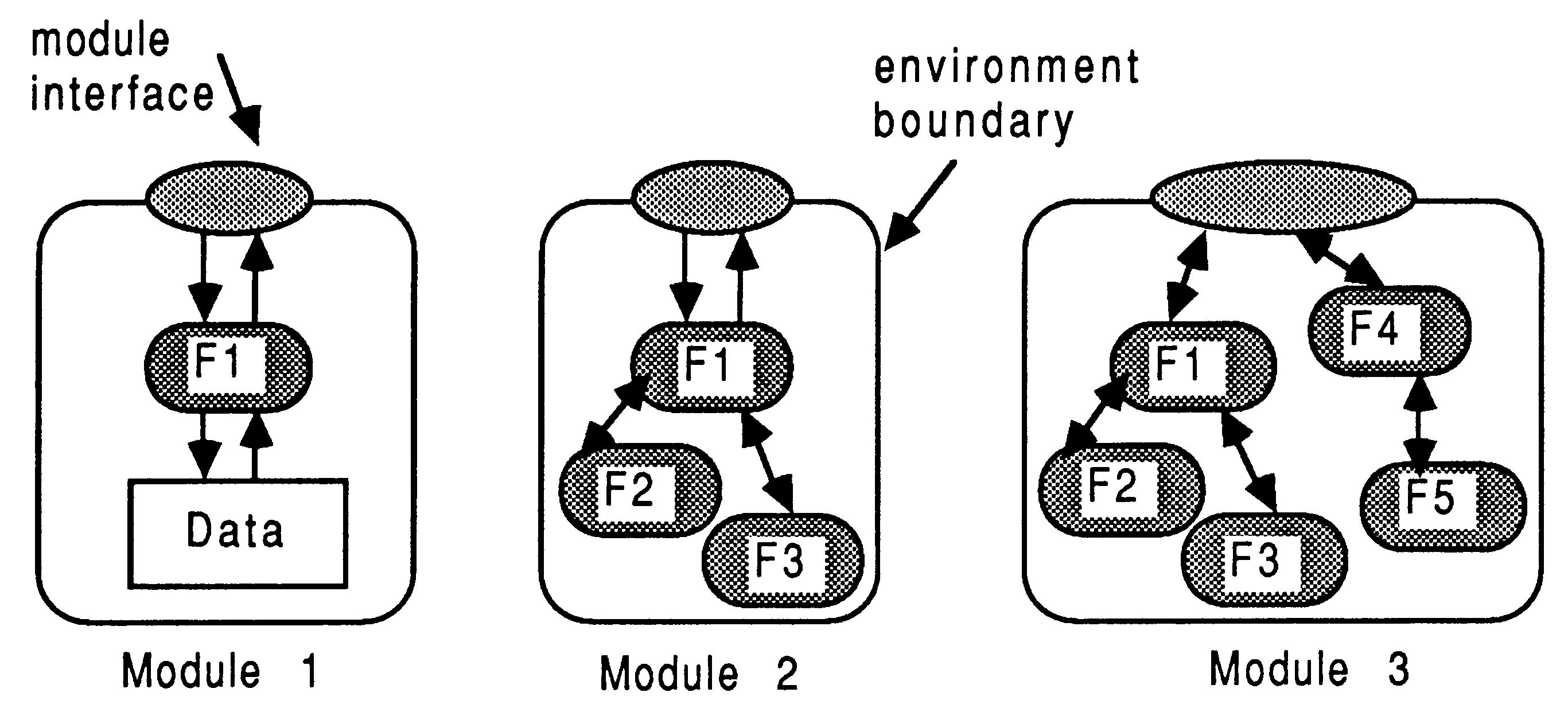
Concerning the collection of functions contained within a module, consider Figure 5.
With reference to the Figure, the small shaded rounded boxes represent functions, and the large unshaded boxes represent the boundaries of a module. Three different modules are shown
A module would generally contain many functions and function groupings.
Modules require some supporting occam, known as the harness. The harness can be thought of at two levels. Each module is firstly enclosed in an occam wrapping which allocates workspace to satisfy the stack and heap requirements of the module. This harness and the module together represent an equivalent occam process (EOP). It is written as a PROC, allowing it to easily connect to other EOPs using only channels. Then, all the EOPs are interconnected using a top-level harness, one per-transputer. Refer to [3] for guidelines on all aspects of harnessing.
Modules communicate by passing messages. Modules can utilize an arbitrary number of channels to communicate externally. These channels are set-up by the occam harness.
Occam statements are used to control execution of each EOP module. Because all the useful application code is confined to non-occam modules, the system instantiation pattern is for the occam top-level harness to instance all modules together in parallel at the start of system execution, and let the application control itself until termination.
... define interconnect channels
PAR ... instance module 1 ... instance module 2 ... instance module 3 |
Once a module terminates, it cannot be restarted under the control of module. Only occam can be used to instance a module.
A module has to be structured such that once it is entered (upon instantiation by the occam code), it does not terminate until the application has finished with it. It is useful at this point to compare the temporal existence of modules and functions.
Modules communicate with other modules using messages sent on channels. Absolutely anything non-local that is required by a sub-ordinate module must be copied from the super-ordinate module into the local environment. This falls into two categories
Some data items will only have to be read into the module, and not exported afterwards. Examples of this would be ”value” parameters and free variables that are not written to in the module. Some data items must be sent both ways, for example, any ”reference” parameter or written-to free-variables. Non-local data items such as strings and arrays, which are generally referred to by pointers, must have their entire body communicated (both ways if the data item could be written to) instead of the pointer value.
Any data item used outwith the current environment must be message passed for every interaction with the module. The messages represent the values of the parameters and free variables that would have been passed to and from the module if it were still implemented as a function call in a flat system.
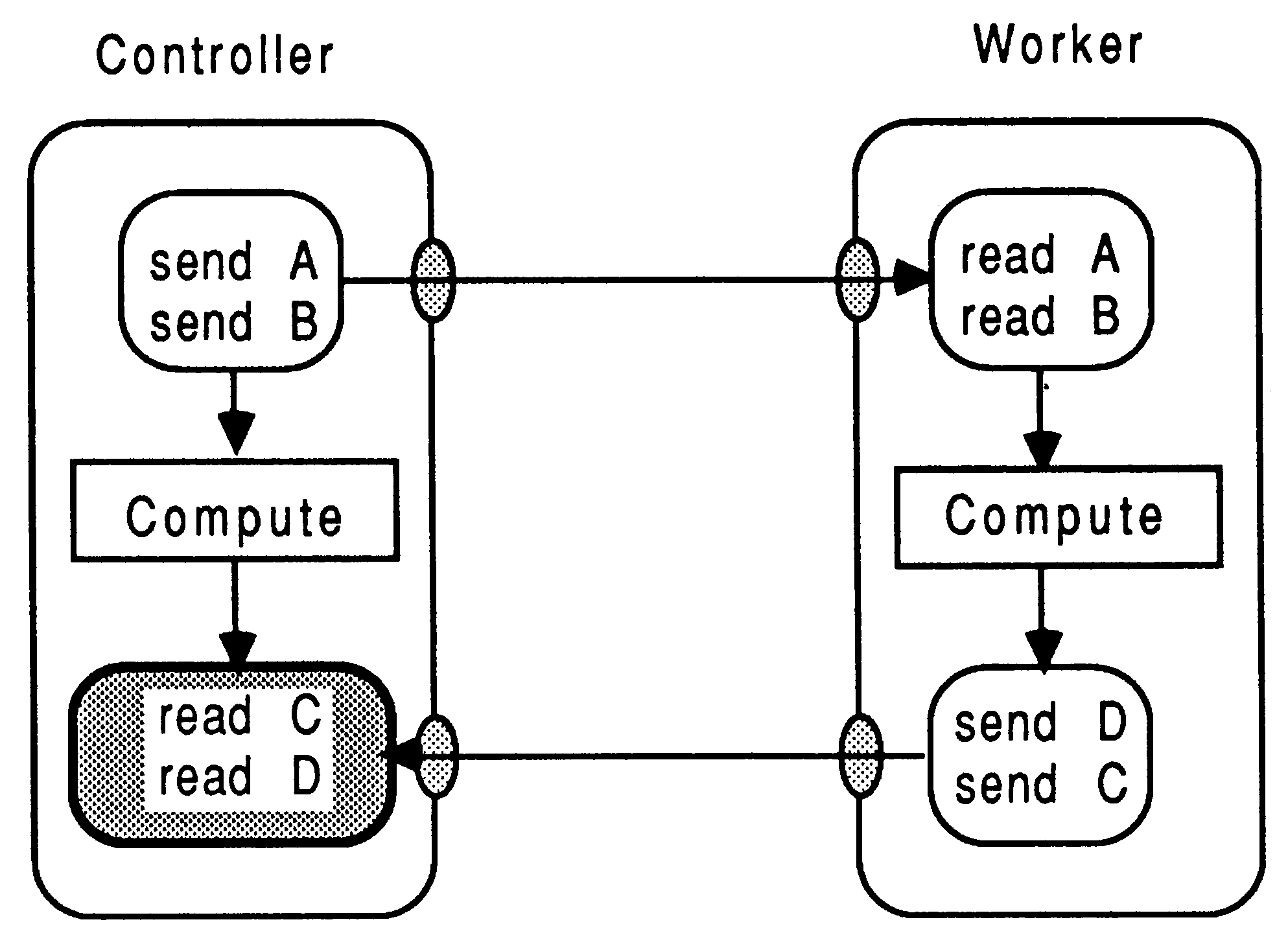
It is vitally important to ensure that each interaction between two modules observes a constant, fixed, defined protocol sequence. This is the only safe way to prevent deadlock, and prevent parameters getting muddled up. For example, Figure 6 shows the consequences of an inconsistent message ordering in the sending and receiving environment. Referring to the Figure, if data elements C and D are the same size, then they will end up at the Controller module having each other’s value. If they have different workspace requirements, then the system will possibly hang, depending on the primitives used at each end to transfer the data - but the results will definitely be incorrect.
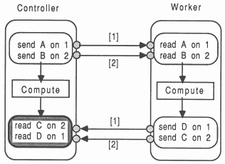
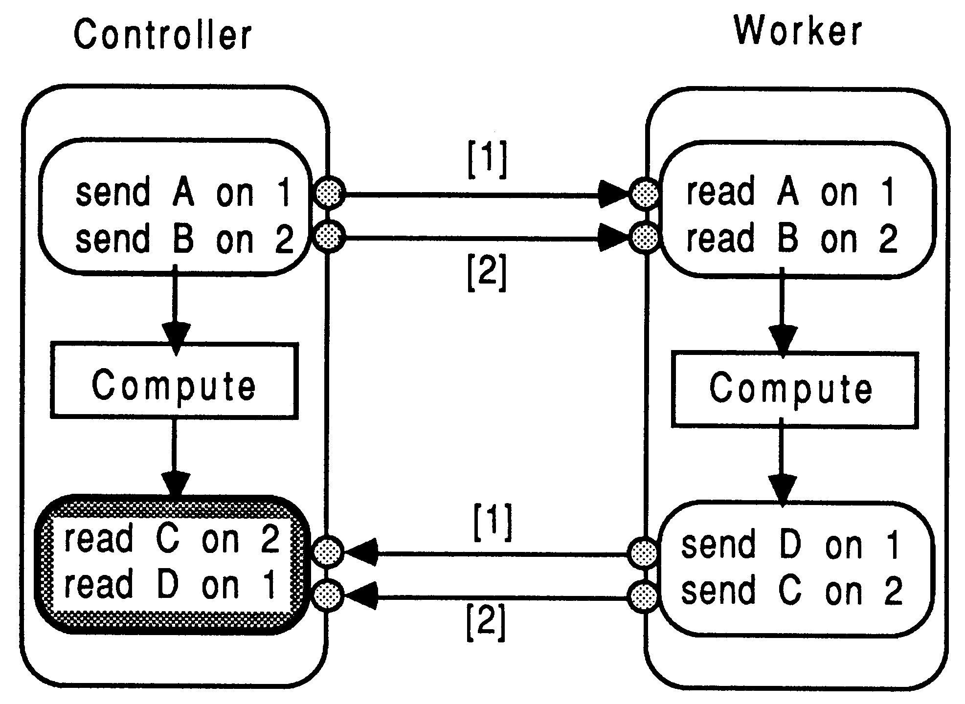
Figure 7 shows a system deadlock, caused by an inconsistent ordering of channel reading, between the sender and receiver modules. Although the Worker and Controller are transferring data in the correct order, the deadlock arises from the Worker module sending data on channel 1 while the Controller is waiting on data from channel 2. This data will never arrive on channel 2 because the Worker won’t send anything else until it’s message on channel 1 has been accepted. If the language allowed both transfers to occur in parallel as in occam then there would be no deadlock potential here.
This section discusses some guidelines to follow when planning the decomposition of an application into independent message-passing modules. This part of an application porting is very dependent on the way the application is structured. One must have a knowledge of the data flow within the application to allow effective partitioning of the program into orthogonal modules.
The objectives are that each module performs a lot of computation, but with minimal communication between neighbors.
For example, any construct performing screen, keyboard, or file system interaction is host-dependent. If several modules use full language input / output capabilities, then it is necessary to arrange, by means of multiplexers, for these modules to have a communication path routed to the root module that communicates with the server. Due to the limited number of links on each transputer, it is best to try and avoid the overheads of multiplexing messages along chains of modules. The best approach is to have only the root module performing full language input / output.
Supposing an application has been written in such a way that several clearly delineated operations proceed sequentially. Each operation reads some input from a file, processes it, and writes the results out to another file. A particular speech synthesis system springs to mind. If such an application were to be converted to modules with a view to distributing it across a transputer network, then there would be serious penalties paid for accessing the data files. Several approaches can be taken. One approach is to pay the disk access penalty and arrange for occam software to route messages to the host for file access. Another approach is to tweak the application to write and read from a RAM-resident FIFO data buffer3. This removes the bottlenecks associated with host dependency. A further method is to use the HELIOS transputer operating system to use local processor RAM as disk storage and FIFO.
Note that, a detailed data-flow knowledge of the way the application is written is needed to establish blocks of code that could be completely self-contained, and operate effectively in parallel with other parts.
The usual considerations of module traffic compared to computation performed per access should be used to establish the effectiveness of this grouping. Note that if more than one module requires to access another, a control channel and occam multiplexes, shown in Section 5.3, is required.
For example, a compiler or spreadsheet will contain a number of global data structures. The structures and all functions that operate on them could be packaged up as a module. This ensures consistency and integrity of the data structure and provides a clean, well-documented interface, to the outside world.
It is important to ensure that a different module does not attempt to access any parameters or free variables while they are being used (and possibly altered) by any other environment. This would lead to an inconsistency in the data values, which may not be appropriate behaviour for the application. This is normally prevented by a careful and strategic decomposition of the application, and by using an access protocol that forces read-modify-write operations to the data structure.
If a large collection of unrelated veritable global variables have to be shared amongst a number of concurrent modules, one has to consider the overheads of broadcasting (both ways) the global data. Using protocol to ”lock” access to the module (to prevent unscheduled modifications) can reduce performance because other parts of the system can become blocked. One could decide not to parallelise at the level that would require heavy overheads in frequently broadcasting and receiving global variables. Select a level of modularity that minimizes the traffic on such broadcasts, since these have to be done both ways for each access by a module.
Under very special and limited circumstances, a suitably robust application may not suffer if infrequently the ”most recent” data values held in a large global array are not used for current computations. In this case, given that all the modules using this data structure are actually guaranteed to be executing on the same transputer as the data structure, then the address of the item can be used to directly write into the memory of the (single-copy) data item. This memory is outwith that of the module using the data item. Beware of parallel modules attempting read / modify / write operations, because there will be non-deterministic effects using this technique.
Given that a ported application has been examined with a view to introducing some algorithmic parallelism, the next stage is to implement the identified function groupings as modules. A strategy for implementing the modules with minimal changes to the application is now discussed by way of examples.
The method involves making no changes to the bodies of any functions / procedures, or to the way in which they are normally called. It is unaffected by recursion or un-clean exiting from loops and nested conditional statements. It is independent of the topology of the transputer network. The technique is also appropriate for part-porting situations, described in Chapter 6.
Briefly, the method replaces the call to a function grouping of functions with a message-passing stub, and uses a standard fragment of non-occam code in the called module to re-create the original environment of the function. This offers the immediate benefits of portability of modules throughout the hardware in a system, but without explicit parallelism between modules. Then, by a simple extension of the method, parallelism amongst the modules is introduced, offering even greater performance when used in conjunction with several transputers.
The technique is as follows:
Consider now the benefits provided by the technique.
The technique is a fast and safe way to implement parts of an application in parallel, because:
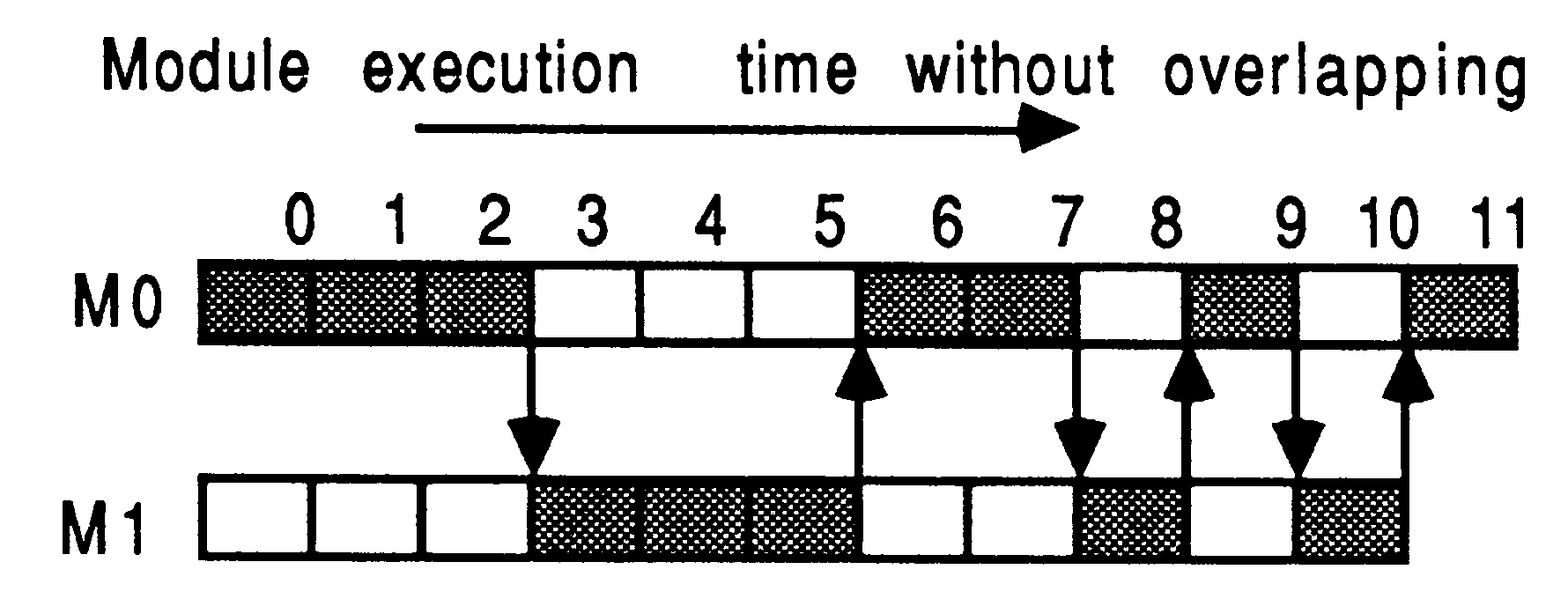
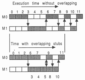
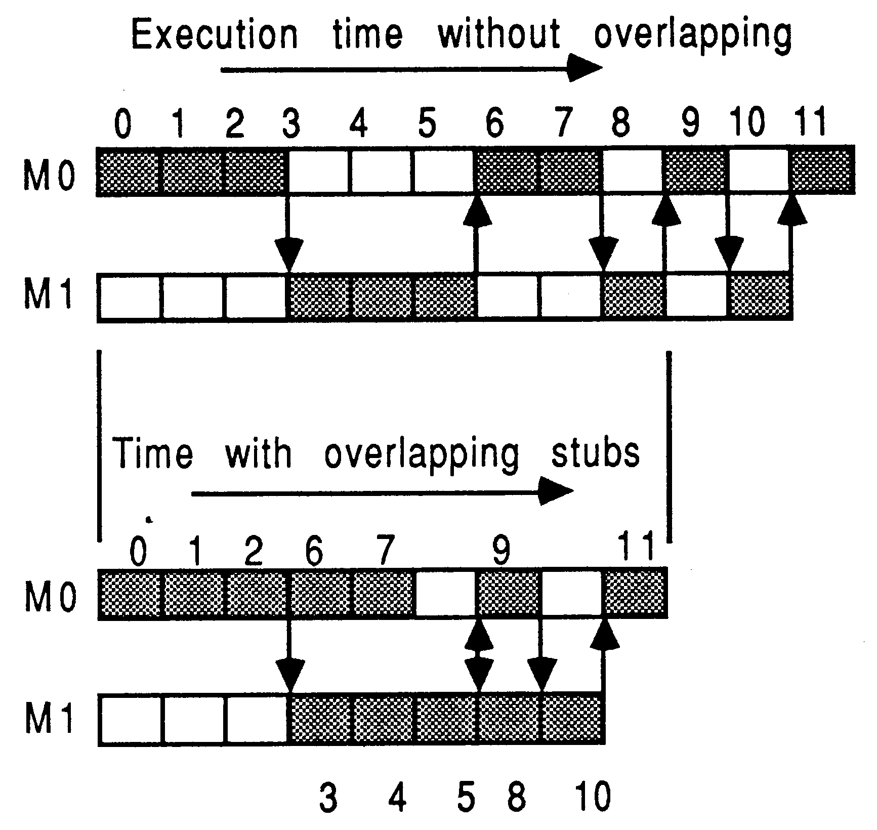
Figure 8 shows how stubs impact the execution of two modules, M0 and M1. The shaded boxes represent active processing. Module M0 processes activities 0, 1, 2, 6, 7, 9, and 11. Module M1 processes activities 3, 4, 5, 8, and 10. Notice that the system about to be described does not yet allow any explicit overlapping of module processing.
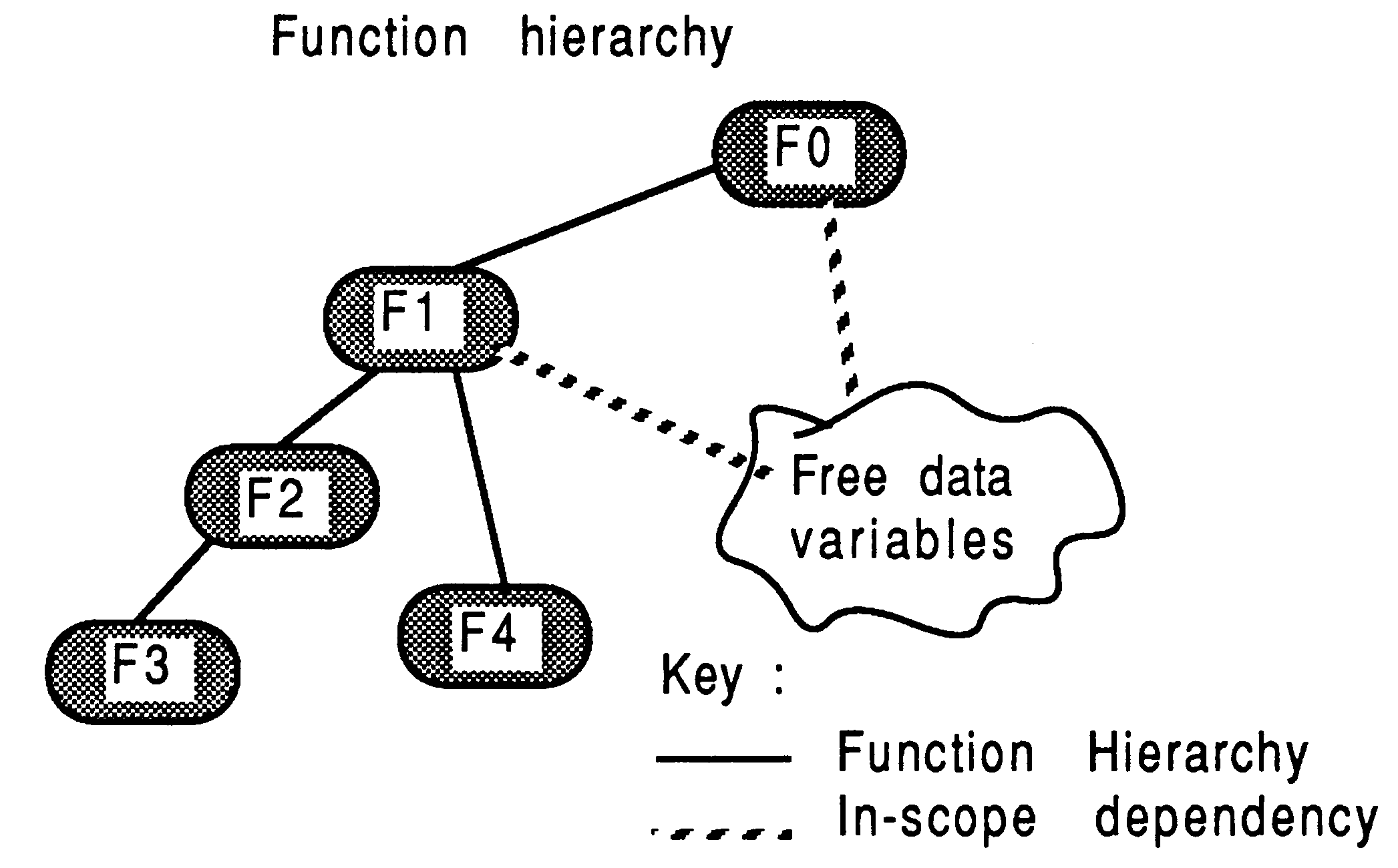
It is assumed that the application has been decomposed into several groups of function hierarchies, as shown in Figure 9. The lines represent hierarchy between the functions, with an implied reference to some free variables (global data).
Function F1 is considered to be the top-level function in the grouping comprising F1, F2, F3, and F4. F1 is itself called from F0, which will be represented by a different module. The method of converting the F1 grouping into a module, and referencing it from the F0 module, will now be discussed, with the objective of not changing the content or declarations of any of the functions l procedures within the F1 grouping, and also not changing any actual ”calls” to the F1 grouping made within F0. These objectives are realized using the technique described above.
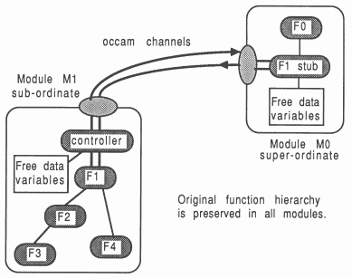
The creation of a sub-ordinate module (M1) and its reference from a super-ordinate (M0) are explained. An overview of what the two module system will become is given in Figure 10.
In the pre-modular system, suppose the C function F1() looks something like this:
int F1(param1, param2, param3, param4)
int param1, *param2; double *param3; char param4[]; { ... local variables defined and initialized ... COMPUTE !! (Calls to F2, F3, and F4) return (answer) } |
F1 is the top-level function in this grouping. It references functions F2, F3, and F4.
The M1 module consists of F1, F2, F3, and F4. The call to F1 is enclosed by a controller loop, to ensure the module never terminates until specifically instructed. This is represented by the controller in Figure 10. Because the functions are written in C, the standard structure for M1 is also written in C:
main(argc, argv, envp, in, inlen, out, outlen)
int argc, inlen, outlen; char *argv[], *envp[]; CHAN *in[], *out[]; { int running = 1, tag; ... decls for non-local data while (running) /** main loop **/ { ... receive tag from calling process if (tag = COMPUTE) { ... receive and unpack data from super-o F1(value, &reference, &bigref, string) ... pack and return data to super-o } else if (tag = INITIALIZE) ... receive and unpack data from super-o else running = 0; /** termination **/ } } ... source for F1 and dependent functions |
Using this arrangement for calling F1 means that none of the bodies or parameters for any of the constituent functions in the module need be changed. All parameters needed are received and unpacked by the surrounding controller loop. All non-parameter variables required are also received as messages and made available in the background, exactly as in the original environment. All results and changed free variables are packaged and returned as messages to the stub that ”called” the module. Don’t worry about the arguments to main () they are required to allow the message communications [3].
In effect, the structure described above creates the exact environment that the function would have experienced in its original place.
The M0 super-ordinate module contains a stub function F1 which takes the same parameters as the original F1. Its purpose is to perform message-based communication with the M1 module. The structure of the F1 stub could look like this:
int F1(param1, param2, param3, param4)
int param1, *param2; double *param3; char param4[]; { ... send messages to M1 module ... receive messages from M1 module return(answer) } |
The stub contains only the message passing aspects required by the real body of F1 in the other module. Figure 10 shows the stub of F1 being called from F0. The actual computation, originally performed by F1, is now performed by module M1, also shown in Figure 10.
This technique can be applied to software being used with any of the INMOS development systems.
There are a few general implementation points to note here
It is important to convert the most subordinate items into modules first. This is so that when a super-ordinate item refers to functions within a sub-ordinate module, all the sub-ordinate’s access channels and protocols will have already been defined - all the information required to reference the other module is available.
It is advisable to use the equivalent of an occam tagged protocol when defining the protocol for access to a module. As well as identifying which one of several possible senior functions is to be executed, it is easily extended to incorporate new facilities. For example, module termination is cleanly addressed using this technique, simply by the use of an additional tag. It also simplifies including a module loop-back ”debugging” mode which can be used to test that messages are being sent, modified, and returned correctly.
In this example, the tag INITIALIZE is used to handle an infrequent distribution of system data which does not form part of the regular interchanges with the module (to minimize traffic). Here is an outline for the controller loop in a module. Notice how simple it is to implement a termination tag.
main( ... )
{ int running = 1, tag; while (running) { ... receive tag from super-o module switch (tag) { case COMPUTE: ... handle computation request break; case INITIALIZE: ... handle initialization request break; case NEWMODE5: ... handle this computation request break; case DEBUG: ... handle debug mode request break; case TERMINATE: ... handle termination /** sets running = 0 **/ /** may propagate terminate signal **/ break; } /* switch */ } /* while */ } |
The COMPUTE tag could indicate normal work for the process, and would invoke a standard message interchange between the calling module and called module. Imported free variables would be declared outside of main (), and assigned to as part of the message input protocol. The DEBUG tag could be used to select a different operation mode tuned to debugging, perhaps to produce additional message traffic or return checkable results. A retro-fitted function grouping could be accessed with NEWMODE5.
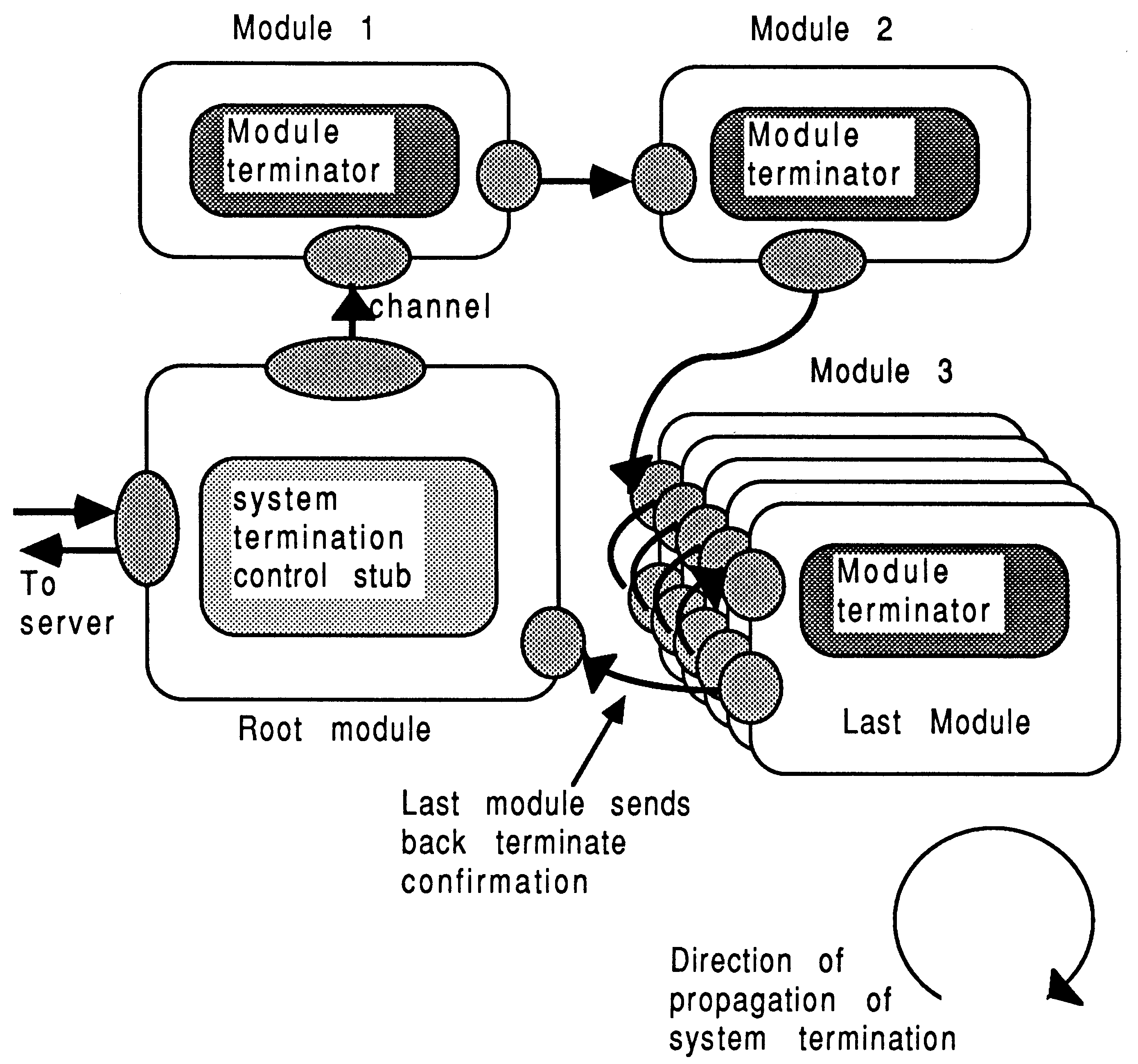
It is important that all processes in a transputer system complete their application processing cleanly. This is often done by the root module initiating a termination condition which spreads to each module in the system on a predetermined route. This option is pursued in Figure 11, where the termination signal propagates clockwise from the root module. This can be implemented using a termination tag described above, which. is forwarded to sub-ordinate modules from super-ordinates.
The shut-down is more secure if each module handshakes the shut-down with all it’s sub-ordinates before handshaking with it’s own super-ordinate. Modules are therefore shut down remotest first.
It is possible to arrange for the root module to send a terminate command to the host server, and neglect to shut down any of the modules. This causes control to be returned to the host operating system, but the transputer network is left running. This can allow the system to be re-run without re-booting the transputers.
Once F1 has been implemented using a stub, it means that within the system, as a whole, there are two entities called F1. One is the original, real, F1, and the other is the stub used to call it. This does not lead to any name-clash problems, because each module is separately compiled and linked before inclusion to the rest of the system.
In general, names of stubs, real functions, or data item do not clash with those in other modules.
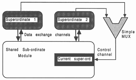
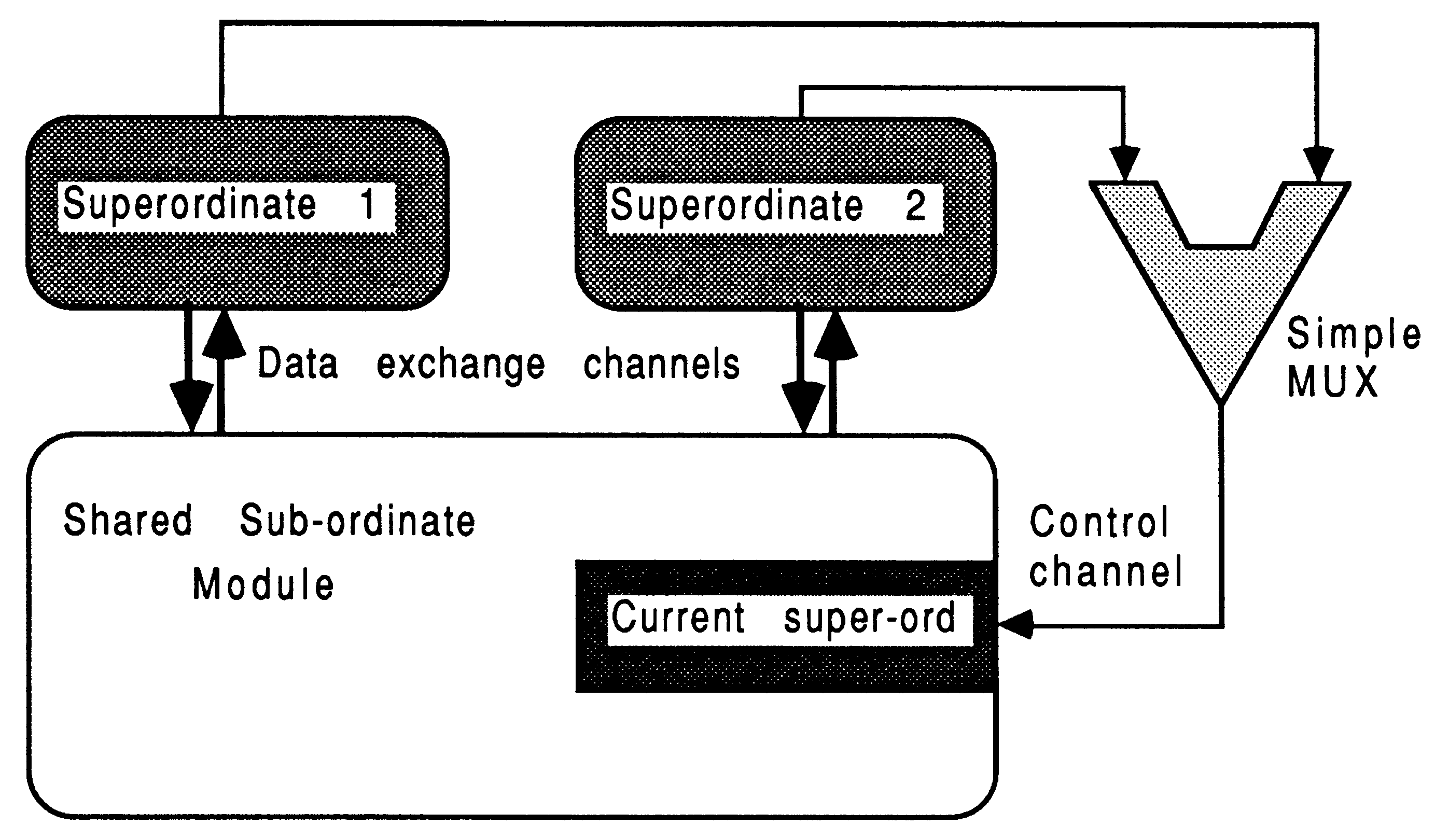
If a module has to be accessed from many super-ordinate modules, then it is important to realize that all the tag messages will be sent on the same channel. This is because most non-occam languages do not permit the simultaneous testing of data arrival on several channels (akin to the occam ALT). A simple occam ALT would be used to funnel access request tags from all super ordinates to the module. A module expecting access from several super-ordinates has, as part of the access protocol, an identification tag which it uses to select channels for communication with the successful super-ordinate. The actual data messages (i.e., everything except the tag) travel on different channels, an input and an output channel per super-ordinate. Only the identity of the current super-ordinate must be sent on the same channel, which is why a simple occam ALT is used to select one of several.
This is shown in Figure 12.
To terminate the multiplexes, one of the super-ordinates should have an additional channel, and as part of its termination protocol it terminates the multiplexes.
If a large global compile-time constant base exists with respect to a number of modules, that has to be available to a system of processes, then the easiest way to handle this is to place definitions shared between several modules in an #include file (for C and Pascal). With C, the pre-processor #define facility would be used to prevent declaring run-time storage for any of these constants.
In this way, changes to the values of any compile-time constants can be easily made available to all separately compiled modules that need them. Unfortunately, the V1.1 FORTRAN compiler does not support file inclusion mechanisms because this is not part of the ANSI X3.9-1978 standard4, so one would have to make explicit textual inserts for all global constants (which would probably take the form of COMMON and PARAMETER statements).
Since compile-time constants, such as C’s #define do not occupy any storage, there is no penalty in having them #included in lots of modules.
Note that with the current INMOS C compilers (V1 .3 and 2.00), static initialized arrays are implemented inefficiently with respect to the size of boot file. A static initialized image is stored with the bootable code, meaning that large arrays lead to large boot files. Try to avoid using static initialized arrays, especially those defined across several modules.
To ensure the integrity and consistency of run-time initialized data shared between several modules, with each module performing the initialization rather than a broadcast reception, any source code shared by more than one module should be #included. This ensures that all modules supposed to hold the same data actually do.
There are cases where the infrequent broadcasting of global constants, which are initialized at run time by another module, is very useful. For example, where a module has to perform some intensive computations to initialize a data structure which is thereafter unaltered but shared between several other modules. Another example might be where a shared read-only database has to be loaded once from slow disk drives and is broadcast once to modules requiring it.
In these situations, this information can be broadcast once only to all the modules that require it, allowing smaller message protocols to be used for all subsequent interactions.
It is straight-forward to implement any number of these data broadcasts, using the tagged message protocol described. The sizes of these broadcasts are not so important because of their infrequency of occurrence (usually only once), and also because the transputer can overlap computation with message passing. Each module in the system may require a different set of global constants to be sent to it, because the concept of globality is made with respect to the given module.
If the initialization of the run-time shared constants is trivial in the computation sense, then instead of calculating once and broadcasting, each module can calculate locally as well as store locally. If too many modules require frequent access to shared run-time constants, then the application may be better decomposed.
This section contains some coding examples of handling parameters and accessing non-local environment data, with stubs and the message-passing functions. The examples are trivial, in that they only show the handling of a single type of parameter or free variable at once. However, by combining the techniques shown, the interface to a module of any complexity can be derived.
Consider again the F1 function grouping in module M1, being called from function F0 in Module M0. These examples assume that communications between the modules take place using element 2 of the input and output channel vectors of each module. So, the C examples use out[2] and in[2] for communication, using messaging functions called _inmess and _outmess from the C run-time library. Although not shown, each sub-ordinate message fragment is within the main controller loop to ensure services are available until the module is instructed to terminate.
A value parameter is one for which any changes that may occur to it in a function / procedure, are not reflected back to the caller. In C, consider a real value parameter called by_value sent by the stub F1 in module M0 as follows:
int F1(by_value) /** stub **/
float by_value; { _outword(COMPUTE , out[2]); _outword(by_value, out[2]); } |
This would be received by the co-ordinator in sub-ordinate module M1 as follows:
float by_value; /** local storage **/
{ _inmess(in[2], &by_value, 4); F1(by_value); } ... Body of F1 in here |
This is the mechanism used for all scalar value parameters. Consider the same situation in Pascal. Here is the stub, placed in the calling module:
procedure F1 (ByValue:real); {stub}
begin outmess(channel, COMPUTE, 4); outmess(channel, ByValue, 4); end; |
This would be received by the co-ordinator in sub-ordinate module M1 as follows:
... Body of F1 in here
var ByValue:real; {local storage} begin {main body} inmess(channel, ByValue, 4); F1(ByValue); end. |
A reference parameter is one for which any changes that may occur to it in a function / procedure, are propagated back to the caller. In C, this is implemented by passing in the address of the item to be used, allowing changes to be directly written into that item. With modules, the actual data (and not just the reference to it) must be passed. Here, a reference parameter called by_ref is sent by the stub F1 in module M0 as follows:
int F1(by_ref) /** stub **/
int *by_ref; { _outword(COMPUTE, out[2]); _outword(*by_ref, out[2]); /* sent data */ _inmess(in[2], by_ref, 4); /* received data */ } |
Notice that the new value for the changed parameter is slotted back into the same memory location as original - the stub does not declare additional storage for it.
The corresponding communications in the co-ordinator in sub-ordinate module M1 are as follows:
main( ... )
{ int by_ref; /** local storage **/ _inmess(in[2], &by_ref, 4); F1(&by_ref); /** call FS the same way! **/ _outmess(out[2], &by_ref, 4); } ... Body of F1 in here |
Parameters that are not four bytes long are handled exactly the same way as four byte parameters, except that the predefines _inmess and _outmess are used. All parameters can be handled this way, even complex records and structures.
In Pascal, the situation is very similar to that in the previous section, except that the Pascal keyword var, used to define reference parameters, indicates that the value must form part of the outgoing message protocol as well as the incoming message protocol.
With FORTRAN, all parameters are passed by reference. Examination of the code would indicate whether the parameter must be returned to the calling environment, or whether it can never be changed.
Supposing F1 happened to return a function value, which may have been used in the original environment like this:
answer = F1(&by_ref);
|
This is easily implemented using the stub approach. An extra message is used in the communications protocol for the result. The stub in the super-ordinate becomes:
int F1(by_ref) /** stub **/
int *by_ref; { int result; /** F1’s return value **/ _outword(COMPUTE, out[2]); _outword(*by_ref, out[2]); /* sent data */ _inmess(in[2], by_ref, 4); /* received data */ _inmess(in[2], &result, 4); return(result); } |
Here, the stub declares local storage for the return parameter.
The corresponding communications in the co-ordinator in sub-ordinate module M1 are as follows:
main( ... )
{ int by_ref, answer; /** local storage **/ _inmess(in[2], &by_ref, 4); answer = F1(&by_ref); /** call F1 the same way! **/ _outmess(out[2], &by_ref, 4); _outmess(out[2], &answer, 4); } ... Body of F1 in here |
Variable length messages, for example, strings, must be handled by sending as part of the protocol the length of the string to send. By specifying the length of the string before the actual byte vector containing the data, source and destination modules always know how much data to expect.
A particular efficiency observation is appropriate for C programs. Rather than use the C function strlen() to calculate the current size of the string, it is faster to block-send the entire area reserved for the string. As well as avoiding timely computation in determining the string size, the block transfer can be overlapped with useful computation in other modules. This is true even for strings occupying only a small part of their reserved storage area.
In C, the zero byte (’\0’) is used to denote the end-of-string sentinel. In occam and other languages, this is not necessarily the case. Therefore, a little recipient-end processing is useful. Any C recipient module receiving from a non-C module must append the zero byte sentinel before availing the string to any other C routines. The position can be determined from the length information prepended to the communication.
As an example of handling strings, consider a C source and C destination module. The constant MAXSTRINGSIZE is declared in both modules at compile-time. Here is the code for the stub in the source module:
int F1(string) /** stub **/
char string[]; { _outword(COMPUTE, out[2]); _outmess(out[2], string, MAXSTRINGSIZE); _inmess( in[2], string, MAXSTRINGSIZE); } |
The C destination sub-ordinate contains the following:
main( ... )
{ char newstring[MAXSTRINGSIZE]; /** local storage **/ int len; _inmess( in[2], newstring, len); F1(newstring); _outmess(out[2], newstring, len); } ... F1 body in here |
If the source module were not implemented in C, the zero byte sentinel should be appended in the C destination. This would also require the transmission of the true length of the string, rather than the maximum possible length.
Similarly to strings, any items that are referenced by pointers, either through parameters or free variables must be sent in their entirety. If any alteration could be made, the entire item must be passed back to the calling process after use. As an example, consider a small array of double-length floating point numbers required by a C module environment. Given that the number of elements in the array is declared as a #define compile-time constant called SIZE_VEC, then the stub in the calling environment might look like this:
int F1(dbl_array) /** stub **/
double dbl_array[]; { int i; _outword(COMPUTE, out[2]) ; for (i=0; i<SIZE_VEC; i++) _outmess(out[2], dbl_array[i], 8); for (i=0; i<SIZE_VEC; i++) _inmess( out[2], dbl_array[i], 8); } |
Each element of the array occupies 8 bytes, and is accordingly handled by the _inmess and _outmess routines. It is not necessary to send the size of the array with the transmission, because the C destination must know this in order to declare a suitable amount of local environment storage (achieved using the #define usage described earlier).
The C sub-ordinate destination may contain the following:
main( ... )
{ double dbl_array[SIZE_VEC]; /** local storage **/ for (i=0; i<SIZE_VEC; i++) _inmess( out[2], dbl_array[i], 8); F1(dbl_array); for (i=0; i<SIZE_VEC; i++) _outmess(out[2], dbl-array[i], 8); } |
If the size of the array were not specified in a #define statement, then it is necessary for the stub message protocol to include the number of elements being transported at each usage - as an additional parameter. Ensure that a sufficient maximum local memory is declared to accommodate the biggest ever array transfer.
An observation on efficiency is appropriate. All array elements are stored contiguously. If the sub ordinate and super-ordinate modules allocate array storage ”compatibly”, then it would be advisable to block-send the appropriate number of bytes occupied by the array, in one operation. Again, this avoids computation and looping overheads. This is straight-forward if the two modules are written in the same language. If this is not the case, differences in the number of bytes per element, array index subscripting, and mufti-dimensional storage must be accommodated.
If a pointer happens to point to an actual function rather than data (as permitted in C for example), then this would be a good instance of including that function in the same module as the one that references it by a pointer, rather than in different modules.
To avoid the overheads of sending strings and arrays as messages, a short-cut is possible if it is guaranteed that the participating modules are resident on the same transputer. In this case, the start address of the data area may be passed a parameter into another module. This approach can be used in any language, because it is possible to call a C function to determine the address of any data item. Remember - if this approach is used and the modules execute on different transputers, the results will be interesting to say the least.
Once one has a system operating, there are several areas one can explore to increase the system performance, for example, by a greater overlapping execution of interacting modules. Some ideas are explored in this section.
This section lists a few useful techniques for increasing performance in a module-based system.
The use of a single stub to call a module means that explicit execution overlapping between the super-ordinate module and the sub-ordinate module is not possible - the super-ordinate sends messages to the sub-ordinate module then deschedules until the sub-ordinate completes. At the expense of including some additional synchronization code to the application, two stubs per function entry in a module can be used.
The existing function stub in the super-ordinate module is split into two parts. The outgoing message protocol goes in a ”start stub”, having the name originally used to access the module. The incoming messages go in an ”end stub”, with a (uniformly) slightly different but meaningful name. The programmer inserts a ”call’ to the end stub at the latest possible moment in the super-ordinate, following the start call, which serves to prevent the super-ordinate doing anything with results or changed parameters from the sub-ordinate. This allows the super-ordinate to continue processing while the sub-ordinate executes. The performance increase is most apparent when the modules are on separate transputers. The re-synchronization is provided by the occam channel mechanisms. One then still retains all the stub advantages and also has the capability to overlap executions. This is shown in Figure 13. Note that evaluating 6 and 7 does not depend on results of 3, 4, or 5.
Not every function entry point in a module need be converted to two-stubs, and of course neither must every module. The stub technique is a convenient way to achieve this.
The implementation of modules often allows a previously unexploited execution overlap between communicating modules.
For example, a sub-ordinate module could return all results to the super-ordinate module, and then do any house-keeping and re-initialization. In cases where a call to a particular function in a module does not return anything, but just cause some action to be done on a data structure; there is no need to re-synchronize with the super-ordinate module.
If the module access protocol involves many, many wonderful messages, it may be more efficient to package them all up into a byte vector and communicate that in one go. This approach requires that both partners undertake some encoding / decoding of data items. However, since each communication has an associated small overhead in setting it up, regardless of the size of the communication, these overheads are significantly reduced. A further advantage is that this type of protocol is easy to route in farming situations. If the vectors are too large (more than a few Kbytes) then latency penalties may be unacceptable.
Another approach would be to look at the division of the application into modules, since module should be selected so as to be compute-intensive with relatively low inter-module traffic.
In the sub-ordinate module (containing the actual bodies of the function grouping being stubbed), it would be possible to have the message-passing inputs interleaved with calculation (once the identity of the requested service had been established). Similarly, some results may be returnable before the end of the module’s work. If the message protocol is carefully chosen, this can be intermingled with output calculations.
The extent of mingling in either of the above cases requires the programmer to make decisions about the earliest moments that communications can be performed. The modifications to the structure of the functions in the sub-ordinate require to be done only once.
For example, consider a function FX with six parameters and a return value. The first three parameters are part of the module access protocol, the last three and a result are output only. The sub-ordinate scenario might look like this:
while (running) /** main loop **/
{ ... receive command tag from super-o if (tag == DO_FX) { ... read a, b, c from super-o result = FX(a, b, c, &d, &e, &f) ... write d, e, f, result to super-o } ... else other things } ... source for FX(a, b, c, d, e, f) |
By having the protocol changed between the super-ordinate and the sub-ordinate, to facilitate maximum overlap in execution between the two participating modules, the message reception can be interleaved with the body of FX. The body of FX becomes:
int FX()
{ ... get a from super-o ... do calculations ... get c,b from super-o ... do lots of calculations ... send f to super-o ... do even more calculations ... send d, result, and a to super-o } |
This technique will usually result in parameters being transferred in a different order to that in which the function is instanced with.
These ideas are fast, but lead to loss of structure and lose some (or all) of the portability aspects offered by stubs. Basically, these approaches should only be used when one is certain that the communications protocols won’t change between neighbours. The bullets are in order of increasing nastiness!
Using knowledge of when certain items of data are available, it is possible to replace sub-ordinate module access stubs by in-line messaging primitives in the super-ordinate module. This involves sending parameters as soon as they are available, and may even involve interleaving accesses to several sub-ordinate modules at the same time. For maximum effectiveness in module overlap, an in-line code substitution for the message-handling body of each stub must be done, where ever the stub is referenced (i.e. frequently). This can be macro-automated using an interesting text editor, to minimize risk of error. Then, each messaging primitive is pushed as far down the source code as possible, thereby increasing potential module overlap.
While this approach (coupled with the others) introduces the maximum possible opportunity for parallelism in a system (without introducing new modules), it is desperately difficult to modify the communications protocol between neighboring modules. Also, the likelihood of errors and deadlock introduced by unsuspecting subtle modifications to the logic of the application code is increased.
For example, referring to the use of FX in the super-ordinate module, a stub would normally be used to ensure all references to FX conformed to the correct protocol. The FX stub would be frequently used within the module:
while (running) /** super-o **/
{ ... chuff result = FX(a, b, c, &d, &e, &f) ... chuff chuff result = FX(a, b, c, &d, &e, &f) ... chuff chuff chuff result = FX(a, b, c, &d, &e, &f) } |
Using the technique just described would result in this
while (running) /** super-o **/
{ ... chuff ... send a to sub-o ... mingled chuff on outgoing ... send c, b to sub-o ... mingled chuff not involving FX ... receive f from sub-o ... mingled chuff on incoming ... mingled chuff not involving FX ... receive d, result from sub-o ... mingled chuff on incoming ... receive a from sub-0 /* we’ve just done ONE access to FX */ ... do other two accesses in the same way } |
The performance increase at this stage is overshadowed in comparison to the problems that could be introduced. All appeal from the standpoint of maintaining a clear structure and the ease of changing protocols is lost. It’s a lot of work to implement and the code size penalty can be large.
Don’t do it!!
By making assumptions about the way the compilers store data, it is possible to communicate many discrete values as byte vectors and save on the encoding / decoding of parameters. This is done by taking the address of the first of a list of variables, and sending a certain number of bytes of data from that address. The assumptions are that the variables to be transmitted occupy consecutive byte locations (yet could be of mixed type). Remember that currently, successive array elements occupy ascending memory addresses and are allocated from the module’s heap storage [3]. Further, by declaring the data items identically in the destination module, it is possible to stream the byte vector into memory used by the required variables.
This is a very dangerous technique, which is very dependent on the current revision of the compiler being used - INMOS make no guarantees about the persistence of storage allocation strategies between tool releases. This is safest if participating modules are implemented in the same language. Yet, in some situations this is a useful technique.
Only after a single-transputer working system is demonstrable, one may elect to implement the following
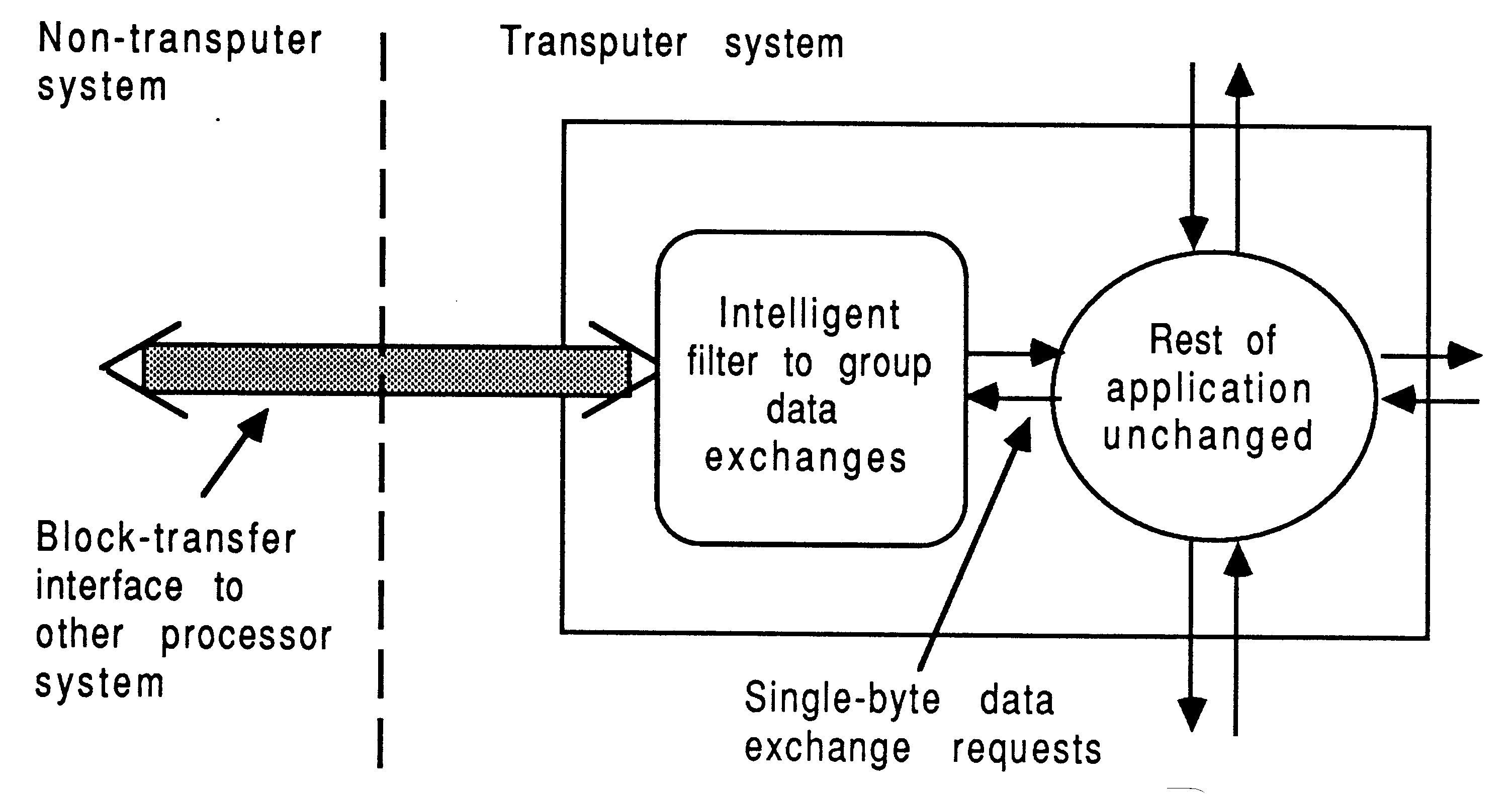
In some applications, it is advisable to consider retaining an original processor in addition to using a transputer. This is known as a part port. In some cases, the other processor will be the host development platform, and in other cases the target environment will be a custom processor card. For the remainder of the discussions on using transputers with other processors, the word processor will be used to refer to a non-transputer processor. The words host and target will be used interchangeably and without loss of generality for the remainder of this document, to indicate processors operating symbiotically with a transputer (network).
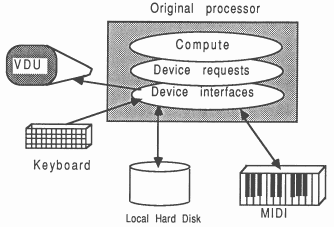
Figure 14 shows an arbitrary processor which interacts with a range of devices and peripherals. A layered software structure is shown.
The lowest-level device driver interfaces operate intimately with the hardware of the original processor. The computation part of the application is quite separate from the low-level interfacing code, and uses clearly identifiable requests to the device handlers to obtain the required device services. The application is independent of the implementation details of these devices.
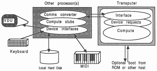
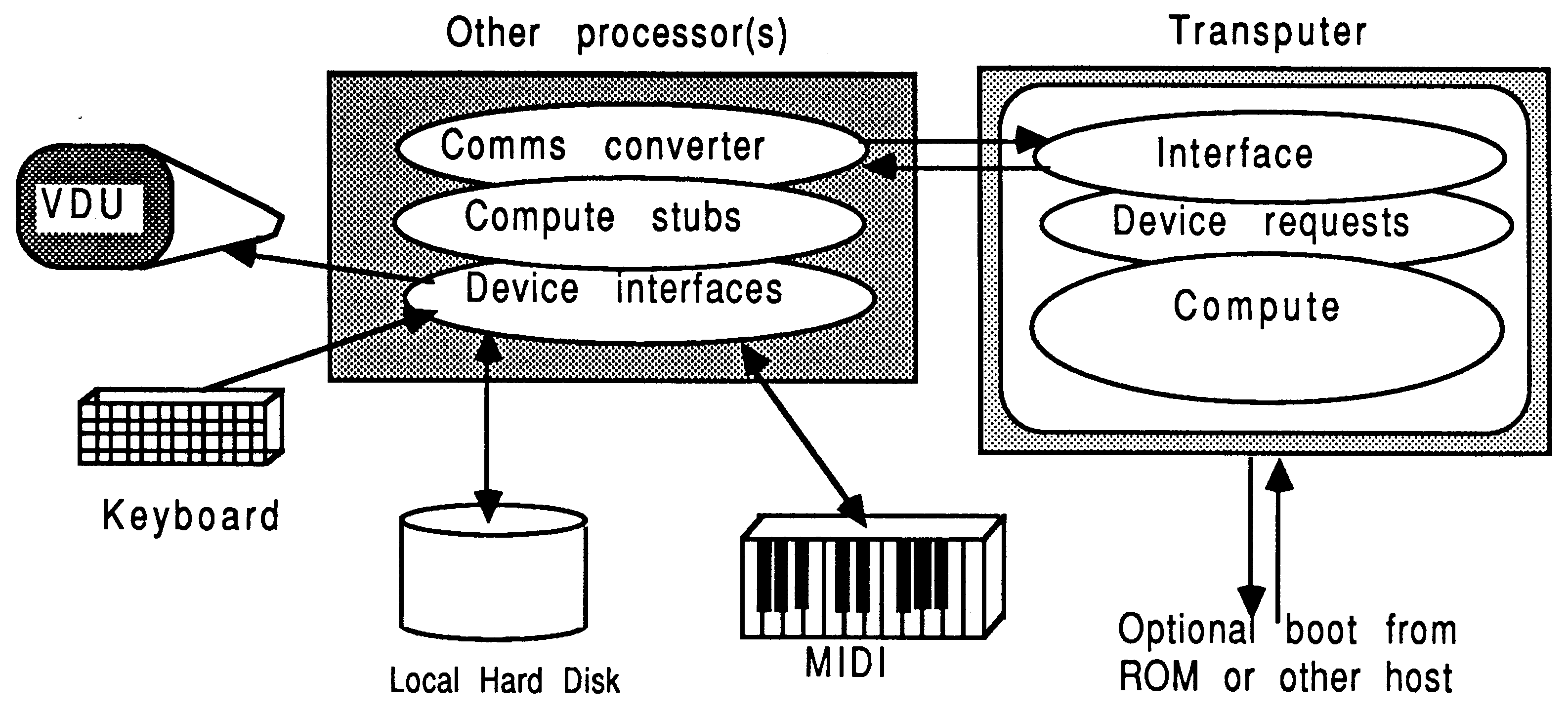
The software situation following a part port is shown in Figure 15. The non-transputer part still handles the machine-dependent interfacing, and need hardly be changed. This saves time in putting together a mixed processor implementation. The lowest-level device handlers are left alone, and the computation parts are replaced by stubs. Before, device requests from the computation part of the application were directly handled by the low-level device drivers. Now, device requests from the computation elements on the transputer pass through a communications medium (a transputer link) and are reproduced exactly on the other processor using the stubs.
The part of the application that is implemented on a transputer is subject to all the previous considerations and techniques in the previous chapter, on the subject of parallelizing an application.
Retaining another processor in a system is sensible in applications that make intricate use of some target dependent facilities, yet are heavily computationally intensive in some clearly identifiable areas. This is often the case in embedded systems, where the transputer can offer invaluable performance rewards.
For example, the following cases could be considered as suitable for partly leaving on host/target hardware in a mixed processor environment:
Envisage a system solution which retains the specialist hardware products currently in use, yet employs a transputer network to increase performance where it’s needed. This is certainly to be advised as a first approach, as the existing hardware investment and interfacing which already operates, is guaranteed to be working.
Some examples of applications which may contain segments to be left undisturbed are those including:
Many non-WIMP user interfaces are assembler-based for responsiveness. For example, the Lotus 1-2-3 spreadsheet user interface. If an application like Lotus were to be ported to transputers, the fast user interface would stay on the host, and the computationally intensive parts would be run on transputers. The result would run faster than implementing the whole application on a transputer, because of the communication overheads between the host and the transputer network. For example, this technique was adopted in Risk Decisions’ ”Predict” Monte-Carlo simulation package.
Working with other processors requires awareness of a few architectural differences that can exist between these processors and the transputer network.
In dealing with mixed processor systems, some software support is required to handle problems presented by the interactions of several heterogeneous processors.
When dealing with other processors, certain inevitable differences between the machine architectures have to be allowed for. These differences are most cleanly handled by the code at each end of the communication link between the target/host and the root transputer, directly involved with data interchanges. This has the effect of minimizing the amount of code that has to accommodate these differences. The differences in question include the following:
Caplin Cybernetics offers a VAX/CSP library package to automatically handle data exchange and format conversion between MicroVAX and a transputer network.
There are some implications concerning the software support required on both processor types if code on one processor references something provided by the other processor. For example, consider the transputer-host relationship:
If the transputer requires any file, screen, or keyboard operations, obtained by calling standard run-time library functions, then host software must be capable of supporting the standard server protocol in addition to any other programmer-defined protocols required by the application9. This implies that, during this time at least, the host software assumes a slave role to the transputer. If this is always the case, then one way to implement this while taking advantage of existing INMOS software is to embody the application within the standard server structure, and simply add any new protocols to the repertoire. This has the further advantage of providing a capability to boot the transputer code and ”serve” it in one neat manoeuvre. However, if the host code is normally the master of the pair, then it may be easier to embody all relevant parts of the server (to provide protocol support) into the host part of application (rather than the other way round which has just been described). In this scheme, the host part will temporarily delegate master status to the transputer while the server communications are under way.
In the relationship between the transputer and other non-host processors, a custom protocol must be devised to allow the partners to request services provided by the other. As long as all partners are kept synchronized to the extent of one master and one slave at any one time for any one communication, there should be no problems. Once this synchronization is achieved, a simple stub technique like that used on a wholly-transputer system offers little disruption to the actual operation of the functions being performed remotely.
The interface between a transputer network and any other processor is normally achieved by using an INMOS link adapter10. This is a byte-wide peripheral that is memory-mapped into the I/O address space of the other processor. It can be read from or written to by the other processor, in the same way as for other peripherals.
The first step to implementing a transputer to any foreign host would be to establish operation of a link adapter. This then permits both processor types to communicate. The rest involves writing software to exchange data meaningfully, bearing in mind the architectural differences that may exist.
Depending on the total system scenario, it may be necessary to permit the other processor to reset or analyse the transputer at will, or to boot code into it, or monitor the error flag11. These supervisor functions are most easily accommodated by mapping in an 8-bit register (in addition to the link adapter), at a different address of course. Reference to any INMOS board-product documentation will demonstrate the relevant hardware techniques. Conformity to the INMOS techniques for implementing link adpater / system supervisory services is advised.
At application run-time, the transputer code must be booted onto the network. If the development host is part of the run-time configuration, then the host can be used to boot the network. The standard toolset server can be used to boot the transputer network, without the need for the programmer to build code into the host part of the application to fulfill this requirement. The host part of the application can then be started up. For example, to boot the transputer with transbit.btl associated with hostbit.exe, the following simple DOS batch file could be used
iserver /sc transbit.btl /sr /sl #300
hostbit |
This has the effect of resetting the root transputer and copying the boot file to it, using the link adapter at address hex 300. In addition to booting the transputer, the target part may also be used to monitor the transputer error flag.
Alternatively, the transputer code can be booted from ROM; this is probably the preferred option in embedded systems. Previously, the technique here was to have the root transputer explicitly boot from ROM by tying the transputer’s BootFromRom pin high. This places certain requirements on where the ROM has to be in the transputer’s memory map, and adds design complexity to the external memory system. However, it is now possible to have a transputer network boot from ROM by streaming the network boot data in any link on the root transputer. Phil Atkin’s published design of a suitable TRAM, called the TransBooter, is given in [9]. As well as simplifying the system design by allowing off-the-shelf only-RAM TRAM boards to be used, the transBooter TRAM also allows fewer ROMS to be employed than would be required in a direct boot from ROM situation (because it doesn’t require word-wide ROMs; only byte-wide), it also overcomes the 64 Kbyte limitation of a 16-bit transputer based BootFromRom system by allowing up to 512 Kbytes of EPROM.
Depending on the physical arrangement of the mixed processor system, some special considerations may be appropriate. The transputer links should be buffered if used between equipment racks, or where the electrical environment is ”noisy”. RS-422 differential transceivers can be used reliably at up to 20 Mbits/second over respectable distances (tens of meters). Fiber-optic communications products should be considered where electrical isolation or greater distances are involved.
As far as the transputer software is concerned, a link is a DMA engine. The other processor(s) can use this to advantage if they have the necessary hardware to support this (i.e., a DMA controller), or they can simply use ”busy” polling techniques to exchange data. There is clearly a performance implication here, which needs some discussion. The subject of heterogeneous processor communication is explored further in the next section.
The transputer communicates with other processors by reading and writing messages down the links. This is how the transputer communicates with the development host, for example. There are several different ways to handle this communication. In each case, any architectural differences between the communicating processors have to be accommodated. Some of these communication methods are described now.
This is the easiest method of communicating between the transputer and another processor. Transputer development boards such as the IMS B004 are communicated with by a host server program using ”polling”. While this is the simplest method for the host to communicate, it is also the slowest. This is because every byte is explicitly transferred and a polled handshaking is in operation (a particular bit a status register port). The ease of accessing port addresses depends on the compiler’s implementation of low-level facilities for the language in question. Some source examples in C and Turbo Pascal of poll-based communication are now given, for use on any processor other than the transputers.
The following examples of C host-source for communicating with the link adapter are taken from INMOS server source:
#define BIT_0 1
int byte_from_link() /* Read a byte from the link adaptor. */ { while (!(inp(link_in_status) & BIT_0)) ; return (inp(link_read)); } void byte_to_link(ch) int ch; /* Write a byte to the link adaptor. */ { while (!(inp(link_out_status) & BIT_0)) ; outp (link_write, ch); } int word_from_link() /* Read a word from the link adaptor. */ /* A host INT is 2 bytes, and a transputer INT is 4 bytes. */ { register int t, ch; t = byte_from_link(); /* l.s. byte */ ch = byte_from_link(); /* m.s. byte */ t = t | ( ch << 8 ); ch = byte_from_link(); /* Ignore upper 16-bits */ ch = byte_from_link(); /* sent by transputer */ return (t); } void word_to_link(w) /* Write a word to the link, least significant byte first. */ /* A host INT is 2 bytes, and a transputer INT is 4 bytes. */ int w; { byte_to_link(w & 0xff); /* l.s. byte */ byte_to_link((w >> 8) & 0xff); /* m.s. byte */ if (w < 0) { byte_to_link(0xff); byte_to_link(0xff); } else { byte_to_link(0); byte_to_link(0); } } |
Notice that the last two functions, word_from_link and word_to_link, accommodate the architectural differences between the transputer and the host, in terms of word length and endian considerations.
The following examples of Pascal host-source for communicating with the link adapter are taken from an example shipped with the IMS B008 PC-format TRAM motherboard:
const
linkBaseAddress = $150; inputData = 0; outputData = 1; inputStatus = 2; outputStatus = 3; procedure outByte (b : integer); begin while not odd (port[linkBaseAddress + outputStatus]) do begin { do nothing } end; port[linkBaseAddress + outputData] := b; end; function inByte : integer; begin while not odd (port[linkBaseAddress + inputStatus]) do begin { nothing } end; inByte:= port[linkBaseAddress + inputData]; end; procedure outWord (w : integer); begin outByte (w and $FF); outByte ((w shr 8) and $FF); if w < 0 then begin outByte ($FF); outByte ($FF); end else begin outByte (0); outByte (0); end; end; function inWord : integer; var b0,b1,junk: integer; begin b0 := inByte; b1 := inByte; junk := inByte; junk := inByte; inWord:= b0 + (b1 shl 8); end; |
Again, the architectural differences are accommodated in these low-level routines. Once written and tested, all communications use these routines. Architectural dependencies are localized.
In communications-limited situations, if several link adapters are available, then it is possible for the other processor to send bytes to each one cyclically (i.e., round-robin), which can almost linearly increase the data transfer rate. This is because time which was previously dead-time is now used productively and once polling begins there is much less time to wait before one can proceed with the next transfer.
For large amounts of traffic, the ”status register polling” technique can be more time consuming than necessary, even with additional link adapters. An alternative technique is to use DMA.
Some INMOS development boards (such as the IMS B008) support a more complex method of data transfer, well suited to moving blocks of memory at high speed, between the host and the transputer. This method is known as DMA (Direct Memory Access), and can be used to achieve higher performance in communication limited situations between the host and transputer (network). It operates by freeing the other processor of the supervising of data transfer, allowing it to do other things in the meantime.
DMA is particularly well suited for large blocks of memory, such as image data perhaps, being transferred from a device on the PC bus to the transputer for processing. This is because the actual data transfer is performed by additional hardware circuitry which supervises the transfer independently of activity on the main host processor. DMA can also be used between the transputer and any other processor in the system, providing each processor concerned is equipped with a DMA controller.
The initialization of a DMA transfer is fully dependent on the DMA controller chip used by each participating processor. It typically involves setting up a few memory-mapped registers, used by the DMA controller, to specify the direction of DMA (i.e., from the transputer to another processor, or the other way round), the number of bytes to transfer, and the address. The memory transfer is then handled invisibly by the DMA controllers. Again, architectural differences between the processor types have to be accommodated.
The performance improvement over the simple polling technique is typically a factor of two, rising for large block movements.
Although this technique is not likely to be applicable to an embedded system, a processor which runs a full general-purpose operating system can offer the previous techniques of polling and DMA transfer implicitly, without the application having to be aware of the mechanisms employed. Assume that the application runs partly on such a processor, and partly on a transputer system.
Many operating systems allow the programmer to add device handling capabilities, known as Device Drivers. They allow any program running on the machine to access the device via the operating system. By using a device driver to handle communications, programs can gain access to the transputer card in an efficient way, without needing to know anything about the specific hardware interface. Caplin Cybernetics implements communication between a transputer network and a MicroVAX using device driver techniques.
In UNIX on a Sun-3, adding new device drivers requires the operating system kernel to be recompiled and linked with the new device driver. In MS-DOS, all device drivers are installed at boot-time, which makes adding new ones simple. There are two distinct kinds of device under MS-DOS:
If an MSDOS character device driver [10] is installed on the PC to service the link adapter, then the host part of the application can communicate with the transputer simply by opening a ”file” and reading l writing data in the normal manner. The transputer software would read and writes bytes to and from the link connected to the host, and form these bytes into the correct numeric representations.
For example, the following fragment of host Turbo Pascal attempts to open a device driver installed under the name of IMS_B004 for reading and writing data to the transputer software:
program DeviceTalkerToTransputer (input, output);
var toLink, fromLink : text ; ... procedure definitions begin writeln (’Device Driven communications’); if fopen (toLink, ’IMS_B004’, ’w’) and fopen (fromLink, ’IMS_B004’, ’r’) then begin ... initialize link adapter and transputer ... perform comma using toLink and fromLink end else writeln (’Error opening link device driver’) end. |
In a PC system, the list of device drivers is specified in the config.sys file. For the link adapter device driver, the configuration file might have this line in it:
device = c:\bin\linkdriver.sys 150 160 IMS_B004
|
The linkdriver.sys file is the device driver image, 150 and 160 represent the link adapter reset and analyse addresses (on the host bus), and IMS_B004 is the name of the device. The INMOS IMS B004 transputer evaluation board uses addresses #150 and #160 on the host PC’s bus. This technique allows the same device driver to be installed, with a different name, at a different address. So, for example, if the same PC had an IMS B008 card at address #300, then the config.sys file could also have this line
device = c:\bin\linkdriver.sys 300 310 IMS_B008
|
To use this environment, the following host Turbo Pascal fragments read and write integers to the transputer:
var
start, finish, i, j : integer; begin ... initializations for i := start to finish do begin write (’sending ’,i); writeln (toLink,i); readln (fromLink,j); writeln (’ .. and received ’,j); end end; |
The communication of these integers must be handled on the transputer by software expecting to send and receive bytes. So, for example, the following occam PROC could be matched to the Turbo Pascal above:
PROC the.transputer.test (CHAN OF BYTE from.link,
CHAN OF BYTE to.link ) #USE "string.lib" PROC readint (CHAN OF BYTE in, INT n) -- convert byte stream into transputer integer [100]BYTE string : INT str.l : BOOL err : SEQ GETSTRING (in, err, str.l, string) STRINGTOINT (err, n, [string FROM 0 FOR str.l]) : PROC writeint (CHAN OF BYTE out, INT n) -- convert transputer integer to a byte stream [100]BYTE string : INT str.l : BOOL err : SEQ INTTOSTRING (str.l, string, n) SEQ i = 0 FOR str.l out ! BYTE string[i] : WHILE TRUE -- main body INT data : SEQ readint (from.link, data) ... operate on data writeint (to.link, data) to.link ! ’*n’ to.link ! ’*c’ -- allows readln in Pascal host : |
The device drivers can be used from any host language supporting file access. By using device drivers and transfering information as ”human-readable” quantities, all the architectural differences between the host and the transputer are nullified, as far as the application programs are concerned. So, considerations for endian, wordlength, and data-type representation incompatibilities are no longer important, as long as the transputer packages up the textual representation of data into suitable transputer format. This has considerable benefit in exchanging floating-point information, but there is an unavoidable inefficiency because more bytes have to be exchanged than for data encoded in the normal host representation.
A further benefit exists when it comes to testing the part ported system. It is possible to test one part without the other, by using real files containing dummy information which represents the data being transcommunicated.
For example, to test the host input and output messaging under a specific execution path, an ASCII file would be prepared containing expected responses from the transputer system. The host would open that file for input in place of the incoming channel from the link adapter. The resulting output communications from the host part can be fed to file and analysed afterwards. Because all data is human-readable, it is easy to prepare and check test cases.
If the hardware implementation of a communications interface between a transputer system and another processor is most efficient at exchanging ”large” data blocks (100 to 10000 bytes say), then performing mostly single-byte transfers is far from ideal. To take best advantage of this, it may be necessary to arrange for the application to perform mostly multiple byte transfers. For example, a typical file loading would sequentially read bytes from a file until the end was reached. By either placing a filter on the channels between the application and the file store, or by adjusting the application slightly, large data blocks can be requested for transfer. The situation is depicted in Figure 16.
The filter technique is application independent. It consists of a software process on the transputer connected to the other processor. The filter detects a request from the transputer application for a byte held (in a file perhaps) on the other processor, and a delay servicing this until the next request has been examined. If the request is exactly the same, the filter blocks these up until (say) 128 byte reads (or writes) have been processed in succession. The filter then arranges for an appropriate interaction with the other processor in an efficient block transfer. If the request is different, it will purge its current backlog. This technique can be used to good advantage on DMA-type interfaces. The overheads in running the filter are dwarfed by the increase in performance due to efficient operation of the inter-processor communications.
The best implementation strategy for a mixed processor system is very similar to the methods of modularizing an application described in the previous chapter. The concept of using message passing stubs in the target parts, and unmodified original parts on the transputers, is unchanged.
There are several areas which could cause problems in a mixed processor system, so a phased testing and implementation is to be recommended. The following ordering is suggested
One unique feature of a system incorporating transputers is the ease by which the system can be investigated by software means when behavior is unexpected. For example, simply connect any unused transputer link to a host platform supporting the iserver, (and arrange for the transputer to boot from link), and wheel in the toolsets’ symbolic debugger. This allows an embedded system to be examined, or to have diagnostic code loaded instead, even if the debugger platform is not part of the normal configuration. A network memory dump can be taken at a remote customer site by a field engineer, and taken back to the laboratory for analysis and reproduction by the debugger.
Once the mixed processor system is operational, and all code intended for transputer targeting is implemented on the transputer, there are some other areas that can be looked into.
The implementation techniques discussed above are now illustrated by considering a Turbo Pascal application on a PC. Part of the application is to be ported and executed on a transputer, using the Transputer Pascal compiler.
Suppose only function HugeTask is to be ported to a transputer. It has two value integer parameters, and returns an integer result. It uses no free variables. The actions of the function are not important. The stub for this, left on the host PC, may look like this.
function HugeTask (a, b : integer) : integer; { stub !! }
begin outWord(OpCalc1); outWord(a); outWord(b); HugeTask := inWord; end; |
The integer tag OpCalc1 is simply used to identify that the HugeTask function is required, rather than some other function which may be subsequently implemented. The procedure outWord and function inWord accommodate architectural differences between the PC and the transputer.
The Pascal on the transputer represents a module. A standard ”entry-point handler” called runController is used to read the tag identifying the action requested, and then passes control to a message-passing procedure for the action; DoHugeTask in this case. This structure allows simple accommodation of many different functions on the transputer:
module remote;
$include ’\tp1v2\channels.inc’ const OutChannel = 2; InChannel = 2; OpCalc1 = 0; function HugeTask (a, b:integer): integer; { Define the original function here } procedure DoHugeTask; { Message handler for HugeTask } var a, b, result:integer; { local storage } begin inmess(InChannel, a, 4); inmess(InChannel, b, 4); result := HugeTask(a, b); outmess(Outchannel, result, 4); end; procedure runcontroller; { Standard component } var stopping : boolean; command : integer; begin { runController } stopping:= FALSE; repeat inmess(InChannel, command, 4); if (command = OpCalc1) then DoHugeTask { List all module entry points here } else stopping := TRUE; until stopping; end; { runcontroller } begin { main } runController; end. |
A standard occam harness connects the Pascal module channels to the link adapter connected to the host.
The same structure of software components is used for any application, in any language. On the other processor, message-passing stubs replace the functions to be ported. On the transputer are placed all the ported functions (like HugeTask), a message-passing handler for each one (DoHugeTask performs communications to reproduce the original environment, calls HugeTask, and sends the results back), and one standard runController framework.
Farming involves using additional processing power (in the form of transputers) to work concurrently on a problem and thereby achieve a performance or through-put increase.
A processor farm consists of a transputer network, frequently of regular topology, which routes work to worker processors and retrieves the results when they are ready. The general farm structure is shown in Figure 17. It is independent of the application, and requires only minimal implementation modifications to a suitable modular application.
In a processor farm, the work to be done for a single job is decomposed into a set of independent tasks which can be executed concurrently, with each processor performing a part of the total task. For example, the Mandelbrot Set [11, 12] is a infamous example of a transputer farm. Each processor calculates a small part of a scene, which is gradually built up in patches. Only a small amount of input data is required to enable a worker to calculate the image for that patch of the total scene. Ray tracing [11, 12]] is another good opportunity for processor farming. A database of world objects is broadcast to all workers. Each processor then computes an image tile for a small segment of the image.
Alternatively, a farm of entire applications can be constructed. This is useful where the same application has to be run many times, each with different sets of input data, and where the outputs can be stored independently (perhaps on the host’s filestore). Each transputer executes the entire application, which is completely unmodified.
Before looking in detail at some different categories of processor farm, consider what affects an application’s suitability for farming.
The requirements for introducing farming to an application include
This section discusses farming in general, beginning with the various components found in a farm. Each transputer in the farm typically executes identical ”worker” code.
There are three key software components in any farm, in addition to the application to be farmed. These are explained with reference to Figure 17.
All these processes are written in occam, but the application itself remains in C, Pascal, or FORTRAN. Each farm worker node requires a router and merger to be run in parallel with the application. The root transputer usually controls the farm, and therefore additionally executes the farm controller process, (although a farm can have it’s root anywhere within a transputer network). Various data buffers employed for performance reasons are not shown in the diagram. Reference [11] gives good advice and many practical examples.
All traffic within the farm should be made to conform to a rigid protocol. The design of the protocol is trivial in relation to the actual application, and can be made independent of the application. The usual procedure is for the protocol to allow control and data information to travel on the same channels. This protocol is a typically variant, with less than five variants. In particular, a Work Request variant would be sent by the farm controller, and accepted by the first available processor; and a Results statement variant would be sent back to the farm controller from a worker. Other variants may allow debugging messages to be transported, and allow the farm to terminate cleanly.
In a farm, results often come back to the controller in a different order to which they were sent. This implies that with each results packet, information must be supplied to allow the non-farmed environment to receive the results and ”put them in the correct place”. A neat way to do this is to consider the specification of the work packet to include any necessary pointers / addresses useful to the receiving process. So, for example, any veritable parameters, results, or free variables passed between the module to be farmed and it’s calling environment, must also have storage addresses sent as part of the work request protocol. These addresses also form part of the results protocol, and allow the receiver outside the farm to store data in specific memory locations. An example of this is given later.
Usually only part of an application is farmed. This requires interfacing to the non-farmed bit. To achieve this, the farm control process has two channels to the outside world - one accepts work requests, and one delivers results. The occam model of communication ensures synchronization between all the participating processes.
There are two cases worth looking at.
The FarmInterface process shown below is sent work requests on CommandToFarm by the rest of the application. Replies from the farm are collated and returned to the application on FarmReply. The farm protocol is defined as farm. p. Work is only injected to the farm if the controller has received a t. ready tag, indicating an available worker. The controller keeps a count of the number of available processors to which work has not yet been dispensed.
PROC FarmInterface (CHAN OF farm.p fromFarm, toFarm,
CHAN OF ANY CommandToFarm, CHAN OF ANY FarmReply) SEQ ... initialise WHILE farmActive PRI ALT -- Test for free workers needing tasks (FreeWorkers > 0) & CommandToFarm ? len::data SEQ ... send work to farm FreeWorkers := FreeWorkers - 1 -- Handle data from farm fromFarm ? CASE t.ready; processor PRI ALT ... if work to send then send it ... remember available worker has no work t.results; processor; len::data FarmReply ! len::data -- data to rest of appl. : |
In the situation where work is being dispensed from a non-transputer processor, the synchronization offered by a purely transputer-based system is lost. The other processor, say the host, in order to synchronize with transputer activity, must be allowed to ”free run” and send task after task to the farm before any results are received. This can be accommodated in a handshaking protocol between the host and the transputer, and encapsulated in a HostInterface process which connects directly to the host and the FarmInterface process.
The HostInterface implementation shown below operates as follows. If a valid job specification is received, it sends it onto the farm directly. If the farm is fully busy, it will be unable to receive any further correspondence from the host. If there are any results from the farm, they are returned as part of the handshaking; otherwise a null result is returned. At the end of the application, this mechanism will have resulted in fewer valid results received than job specifications issued. An enquiry tag t.Enquiry is used to return results if there are any - this can be used by the host until all results have been received.
PROC HostInterface (CHAN OF HostToTP.p fromHost,
CHAN OF TPToHost.p toHost, CHAN OF ANY CommandToFarm, CHAN OF ANY FarmReply) SEQ ... initialize WHILE going SEQ fromHost ? CASE -- Valid job for the farm t.ValidJob; len::data PAR CommandToFarm ! len::data PRI ALT FarmReply ? len2::data2 toHost ! t.ValidResults; len2::data2 TRUE & SKIP -- no results yet toHost ! t.NullResults -- null reply -- Farm enquiry t.Enquiry PRI ALT FarmReply ? len::data toHost ! t.ValidResults; len::data TRUE & SKIP -- no results toHost ! t.NullResults : |
Farming can offer a linear performance increase for an application. In some cases, this can be super-linear. For example, in the ray tracer farm, ten transputers can perform at eleven times that of one transputer. The reasons for this are two-fold. Firstly, the use of each transputer’s on-chip RAM means that more of the ”total” task can be accommodated in ultra-fast memory. Secondly, in any application there is generally an initialization portion which only has to be done once. In the ray-tracing case, the overheads of initialization are minimized because each processor does their own portion.
All routing processes are run at high priority to ensure that traffic is kept moving in the farm. This helps to ensure that workers at the extremities of the farm are kept serviced [13]. If the workspace of the routing processes is in internal on-chip RAM, the latency of response to link inputs is reduced12.
The application code is executed at low priority.
Counted byte vectors are frequently used within farms because this serves to make routing and merging simple, and is more efficient per byte sent - the amount of processing resource used by a communication depends more on the number of communications than the amount of data in each communication. However, for large byte vectors, there is a transfer latency penalty to be paid. By breaking a long message into shorter ones, several processors can transfer the data concurrently which reduces inter-processor latency (this is useful when broadcasting data throughout an array) [12].
There is virtually no overhead in running the additional farm routing and control processes [11]. This is because the transputer can perform communication and computation concurrently and independently of each other. Processes waiting to communicate are descheduled by the transputer hardware, thereby freeing some processor resource for other processes. There is a penalty paid for setting up each communication. This is independent of the amount of data in the communication, favoring the use of efficient counted byte-vector communications protocols.
Software buffers should be used to decouple communication and computation, allowing a greater overlap between them. In particular, buffers should be used on all routing and merging channels to decouple the communications from computation, allowing a very high compute-utilization [11, 12]. Copying data in buffers is inefficient, so a swing-buffer approach would be used - data fills one buffer while work is drawn from another, then the other buffer fills etc. This can have a dramatic effect on the overall system performance [11]. These buffers are easy to implement in occam. For example, work packets can be pre-fetched and buffered locally by each worker transputer. This allows a new work task to begin immediately the old one is completed. Buffering on each input to the merger process allows a greater throughput, again by allowing a new task to begin immediately and achieve computation overlap with communication.
The farm achieves a run-time dynamic load balancing throughout itself, with the whole system keeping itself as busy as possible [13]. This is because workers accept work automatically as and when they finish a work packet. If the time taken to process a work packet is longer than the time taken to receive a new work packet from the controller, then each worker is automatically kept busy all the time. The end-latency in a dynamically load-balanced processor farm is much lower than in a statically load-balanced system.
The following list contains some additional points concerning processor farming:
Armed with this general farm information, it’s time to look at three specific types of farm, and consider how they differ from the general farm discussion above.
Start with an application that has already been ported to a transputer, and has been split into modules. Assume that a module can be assembled that represents the part of the application to be farmed (which is of course very compute intensive in relation to the amount of data that has to be provided with each work task). This might be the case where a non-farmed user interface package dispenses work to a farmable computation module. It could also be a part ported application, providing that not all of the original transputer code is farmed. Figure 18(a) illustrates this situation, with Module D to be farmed. No assumptions are made about other processors the farmed module may require to interact with, but in this case the best results will come from farming a module that directly (or otherwise) makes no accesses to a host processor (because Module D is distant from the host and would require protocol routing on intermediate modules).
The implementation starts with a ported application that has been decomposed into modules. One or more modules will be identified as the part of the application that is to be farmed - the worker; Module D in Figure 18(a).
With reference to Figure 18(b): Between the non-farmed part of the application and the worker module, a farm control module, EC, is written in occam. This communicates with the rest of the application via a stub, in such a way that the channels and protocols to the rest of the application are minimally modified. The farm controller divides the total task into a number of sub-tasks, and injects these into the farm using the Routers R. Module D is replicated in the farm, completely without change. Additionally, the farm controller FC ensures that results, which will be returned in a non-deterministic order via Mergers M, are suitably returned to the rest of the application (the results protocol will include enough information to allow them to be correctly slotted in).
Consider farming an entire application, which is already successfully ported to a single transputer (this precludes a part ported application). The application uses host services, so it is necessary for these host accesses to be correctly interleaved to prevent cross-interference. The application is not modified - it doesn’t even know it’s in a farming environment. With reference to Figure 18(a), this would correspond to farming the whole of Modules A, B, C, and D, with Module A connected to the host. In this case, the controller FC of (b), instead of being a stub to the rest of the application, would enquire of the host the work to be done. The host will provide a list of (independent) tasks to be performed. Each transputer will perform an entire ”application’s worth” of work.
This farm is implemented without modification to the application. Some issues are:
A further technique used here is to give short-circuit replies to the workers in place of the server. The need for this arises because all server communications involve a reply handshake, which is frequently ignored by the application anyway. The server filter can detect the use of commands to which this technique is appropriate, and immediately acknowledge them. Handling commands like this where possible also reduces the amount of traffic in the rest of the network, further contributing to overall performance.
An alternative implementation of a farm requiring many workers to access the host, but requiring no user interaction at all, is to simply use server protocol multiplexers as routers. The multiplexers understand a superset of the standard server protocol (so that workers can ask the farm controller for new tasks when they are ready for work). By ensuring that the route that the worker’s request packet has to travel in order to reach the farm manager is locked by the multiplexes until the farm manager responds, the system avoids having to make routing decisions at each node if the network is not simply linear (e.g., trees, forks, pipes, stars). Although simpler to implement, this type of arrangement will typically give lower performance than the Router/Merger approach.
This approach was used with SPICE in [5] for a simple star network of three worker transputers.
Consider farming any application which co-executes on another processor type, where all the transputer code is to be farmed. The case of farming part of a mixed-processor system is the same as in Section 7.5, because the other processor does not communicate directly with the module to be farmed.
A good starting point for farming a heterogeneous processor application is a working non-farmed system, with the transputer module to be farmed clearly identified.
The host source needs to be altered slightly for maximum effectiveness, because results are likely to be returned out of order. Also, using the HostInterface source shown earlier, does not guarantee that every job request leads to a valid result. The original access protocol between the host and transputer is modified to accommodate out-of-sequence results and dummy results. The protocol still follows the same pattern of an outgoing followed by an incoming sequence, but the important thing is that the incoming message must identify what work packet the result corresponds to, and how to integrate the results into the host environment.
Often, calling a function or procedure causes variables to be written to which are dependent on the value of the parameters at the time off the function call. For example, a parameter i would be passed to a function, and used to reference an array element or scalar variable in the calling environment. Farming will result in out-of-sequence data being returned, which obviously must be used with care in the calling environment. Any writeable variables should be handled by a ResultsManager procedure which ensures that the returned results are correctly matched up with the original parameters, and correctly integrated. To achieve this, additional data is sent to the farm and returned with the results.
Incoming work requests to the farm from the host will be not accepted by the farm controller until there is a worker available (therefore the host can be held up at this point). The host keeps track of how many items the farm is processing, by incrementing a counter each time work is sent to the farm, and decrementing it for every valid reply returned.
For example, consider the farming of the part ported function HugeTask, originally part ported in Section 6.8. The host stub for HugeTask now only handles outgoing messages directly:
procedure HugeTask (a, b:integer); { stub }
begin outbyte(ValidJob); { intercepted by Hostinterface } outword(OpCalc1); { Do HugeTask operation } ... send any info to slot results into original environment outword(a); outword(b); { originally, HugeTask := inWord; } ResultsManager(1); { Handles ALL incoming messages } { The parameter 1 increments what’s in the farm } end; |
Originally HugeTask was a host function. It has been converted to a host procedure to prevent anything writeable being written to directly following execution of HugeTask - this is because the result returned is unlikely to correspond to the same set of parameters as were just sent to the farm. All writeable variables must be handled by the ResultsManager, unless it does not matter in what order the data is written.
To allow the results to be returned out of sequence, a host ResultsManager procedure is used to handle all received handshakes from the transputer farm controller
procedure ResultsManager (AddToFarmCount: integer);
var ... declarations begin InFarm := InFarm + AddToFarmCount; ReplyTag := inbyte; { Valid or not valid results } if (ReplyTag = ValidResults) then begin InFarm := InFarm - 1; Command := inWord; if (Command = OpCalc1) then begin ... receive data from HugeTask operation ... handle all order-sensitive writes end { OpCalc1 } { list other operations here } end { ValidResults } end; |
To purge the farm of all tasks in it, the host PurgeFarm procedure gathers all results together by sending enquiries to the transputer Hostinterface:
procedure PurgeFarm;
begin repeat outbyte(EnqFarm); { intercepted by Hostinterface } ResultsManager(0); until InFarm <= 0 end; |
By altering the application structure slightly, the complexity of a part port farm described above can be reduced to that of just a part port. This is done by arranging that instead of actions on the host (or other processor) directly feeding to the Hostinterface, they instead feed a small stub-like auxiliary routine on the root transputer with a total job specification. By specifying the total amount of work to be done at the outset, the host is freed from the issues of handling out-of-sequence results. The auxiliary routine on the transputer divides up the task into sub-tasks and farms it out to the Farminterface. When all the work is done, the results are packaged up and returned in one consolidated communication to the host. The host part of the application would typically receive an entire array containing all the results in one go.
In this way, the host does not know that farming has occurred, and therefore needs no modification if the original part port was implemented to communicate in this way.
Second Sight13 2 is a Turbo Pascal application, with a snazzy front-end using pull-down menus and host graphics. It analyses sets of data and detects trends in them, allowing forecasting future values. The application is suited to farming, because all the sets of data can be operated on independently and concurrently. The code was split into a computational part that executed on a transputer system (doing data modeling), and a user-interface part that executed on the host (unchanged).
All host service accesses are confined to the host computer itself, thereby obviating the need for a standard server. All message passing between the host and the transputer farm was done according to a custom protocol devised for the application. Using techniques outlined in the previous chapters, message passing stubs in the host part communicated with the real function bodies on the farm. Certain global data items were broadcast to the transputer farm beforehand the application began in earnest.
For speed of implementation, all the functions that were to run on a transputer were grouped as a single process, and a tagged message protocol was used to indicate which function to run at any time.
The work took about longer than normal (two weeks), because the transputer parts had to be converted from Pascal to occam since at the time (1986), the scientific-language tools were not as powerful as they are now.
Second Sight running on a single T414-G20 runs about 10 times faster than an 80286/80287 host combination. One T800 transputer runs about 25 times faster. With four T800-G20 transputers, this figure rose to around a factor 100 performance improvement.
The INMOS development tools are best suited to generating transputer programs for transputer networks of pre-determined size. In other words, prior to run-time, the number and arrangement of transputers is known. Using worm-technology [14], it is possible to write programs that flood-fill a transputer network at boot-time.
The Parallel C and Parallel FORTRAN compilers include utilities for performing a so-called network flood-fill in a homogeneous transputer network. In this way, at boot time all the available processors are utilized depending on their presence, without having to change the software if the hardware arrangement changes. These compilers also support rudimentary but useful farming based on master and worker tasks14. The application makes explicit calls to run-time library functions which transparently farm the total work load specified by the Master task [15].
It is possible to make a transputer network more resilient to the environment by performing all off-chip communications using the link communication recovery facilities. Occam provides a set of procedures which can be used to recover from communications that do not complete successfully for some reason [16, 11]. So, for example, the router and merger processes associated with each farm worker would perform ”safe” communications for off-chip channels.
The incorporation of additional communication facilities is very much like adding another layer of abstraction. Again, this layer is independent of the application. The application does not need to be aware of this additional framework, and therefore doesn’t require modification.
[16] discusses the use of the facilities provided at the occam level. [11] gives a practical application of using safe link communications in a linear topology farm, showing firstly how a system will continue to operate at reduced performance and with loss of data as transputers begin to fail, and then showing how automatic error recovery (as well as detection) can be achieved.
The Parallel C and Parallel FORTRAN run-time libraries allow direct use of link recovery primitives from C and FORTRAN [15]. This approach involves modification to all applications that want to use this facility.
The nature of farming can impose additional demands on the host services, for example, in terms of much greater access to the host file store. In these situations, there are a few practical steps that can be taken in an attempt to alleviate I/O bottleneck problems.
These techniques can also be used to good effect in increasing communications bandwidth between a transputer farm and non-transputer processor.
[12] compares the farming concept with that of introducing pipelining into an application. Pipelining is very dependent on the application, has a throughput limited by the slowest element of the pipeline, and is very sensitive to buffering between stages. However, the code required in each stage of a pipeline is generally less than that for a farm worker. Pipelining also accommodates sequential dependencies in an application which would be difficult to deal with in a processor farm.
Pipelining falls outside the scope of this document.
It is possible to operate a farm of farms, whereby an entire application is farmed, but each application consists of a farm of worker sub-tasks. This would be implemented by getting a farm of non-farmed applications working first. The communications protocol between the application and the farm would be carefully documented. Then, the application itself would be decomposed.
In some cases it is important to get data into or out of a farm in a critical time period. In other words, the latency in moving results about must be minimized. It is possible to construct a farm where instead of routing results (or work specification packets) up and down the farm, a direct link connection between the two participating transputers is transiently established for the duration of the exchange. A necklace is still required to permanently connect all transputers, but this is only used for low-bandwidth connection requests and acknowledges. Figure 19 shows such a dynamic switched farm, where results are directly routed out of the farm. In the Figure, the work request packets are still distributed conventionally.
This hardware could be constructed using an off-the-shelf B008 or B012 TRAM motherboard, which both contain INMOS B004 cross-bar link switches. A dynamic switched farm similar to this was found to give 15% to 20% better performance in a farmed MandelBrot application16.
This document has concentrated on taking existing non-occam applications and showing how they can be executed on transputers in a variety of circumstances. Now, a few reminders are called for concerning how one would structure a new application so as to make a future transition to the transputer architecture easy.
Here is a summary of some key ideas to guide writing a new application:
Existing applications spanning a wide spectrum of target environments are easily adapted to the transputer. Transputer software is fast, expandable, maintainable, and portable.
The techniques described have all been incremental. Each step builds logically on the operable stages before them. Capabilities and sophistication introduced in this phased way minimize the risks of failure and delay in porting, allowing stratification of the amount of effort in a project.
INMOS provide off-the-shelf slot-in hardware and software components to assist with application porting, parallelization, and farming using transputers. On the hardware side is the TRAM module and motherboard range. On the software side is the farming support, mixed-processor communications support, and the development tools.
Together, these provide an unrivaled facility for quickly putting together a cost-effective system tailored to the exact requirements of the application. The modular nature of both the hardware and the software components allow an implementation to adapt to the changing requirements of an application.
[1] Transputer Reference Manual, INMOS Limited, Prentice Hall 1988, ISBN 0.13-929001-X.
[2] Occam-2 Reference Manual, INMOS Limited, Prentice Hall 1988, ISBN 0.13-629312-3.
[3] Using the occam toolset with non-occam applications, INMOS Technical Note 55, Andy Hamilton, INMOS Limited, Bristol.
[4] INMOS Spectrum, containing a brief description of the products in INMOS’ portfolio.
[5] Porting SPICE to the INMOS IMS T800 transputer, INMOS Technical Note 52, Andy Hamilton and Clive Dyson, INMOS Limited, Bristol.
[6] The HELIOS User’s Manual, Perihelion Software Limited.
[7] Fundamentals of Operating Systems, A. M. Lister, University of Queensland, third edition, MacMillan. ISBN 0-333-37097-X, and ISBN 0-333.37098-8 pbk. Refer to Appendix for Monitors.
[8] Program design for concurrent systems, INMOS Technical Note 5, Philip Mattos, INMOS Limited, Bristol.
[9] Interface TRAMs, INMOS Technical Note 42, Phil Atkin, INMOS Limited, Bristol.
[10] Using the IMS M212 with the MS-DOS operating system, INMOS Technical Note 50, Jamie Packer, INMOS Limited, Bristol.
[11] Exploiting concurrency; A Ray tracing Example, INMOS Technical Note 7, Jamie Packer, INMOS Limited, Bristol.
[12] Communicating Process Computers, INMOS Technical Note 22, David May and Roger Shepherd, INMOS Limited, Bristol.
[13] Performance Maximization, INMOS Technical Note 17, Phil Atkin, INMOS Limited, Bristol.
[14] Exploring Multiple TransputerArrays, INMOS Technical Note 24, Neil Miller, INMOS Limited, Bristol.
[15] Parallel C User Guide, 3L Limited, Scotland.
[16] Extraordinary use of transputer links, INMOS Technical Note 1, Roger Shepherd, INMOS Limited, Bristol.
[17] IBM Technical Manual, Personal Computer AT, March 1984, Document 1502494.
[18] Transputer White Pages, Software and Consultants directory, INMOS Limited, Bristol.