|
|
| Using transputers as embedded controllers _____________________________________________________________________ |
| Philip Mattos & Jamie Packer Central Applications Group Bristol April 1989 |
INMOS manufacture a range of high performance microprocessors called transputers [1]. These combine all the essential elements of a computer (processor, memory and I/O) in a single component. Transputers can also include an external memory interface (EMI), to increase the amount of available memory, and possibly other, application specific, hardware. The table below summarises the current range of transputer products:
| Part | Processor | Memory | I/O | Other |
| IMS T222 | 16bit, 10MIPS | 4KB RAM | 4links, 16bit EMI | - |
| IMS T414 | 32bit, 10MIPS | 2KB RAM | 4links, 32bit EMI | - |
| IMS T800 | 32bit, 10MIPS | 4KB RAM | 4links, 32bit EMI | 1MFLOP FPU |
| IMS M212 | 16bit, 10MIPS | 2KB RAM | 2links, 8bit EMI | Disk control |
| 4KB ROM | 2 x 8bit ports | logic | ||
| disk interface | ||||
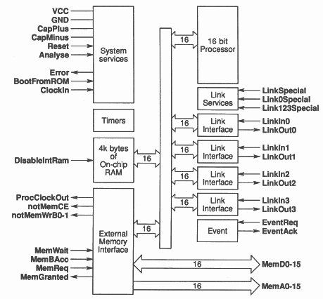
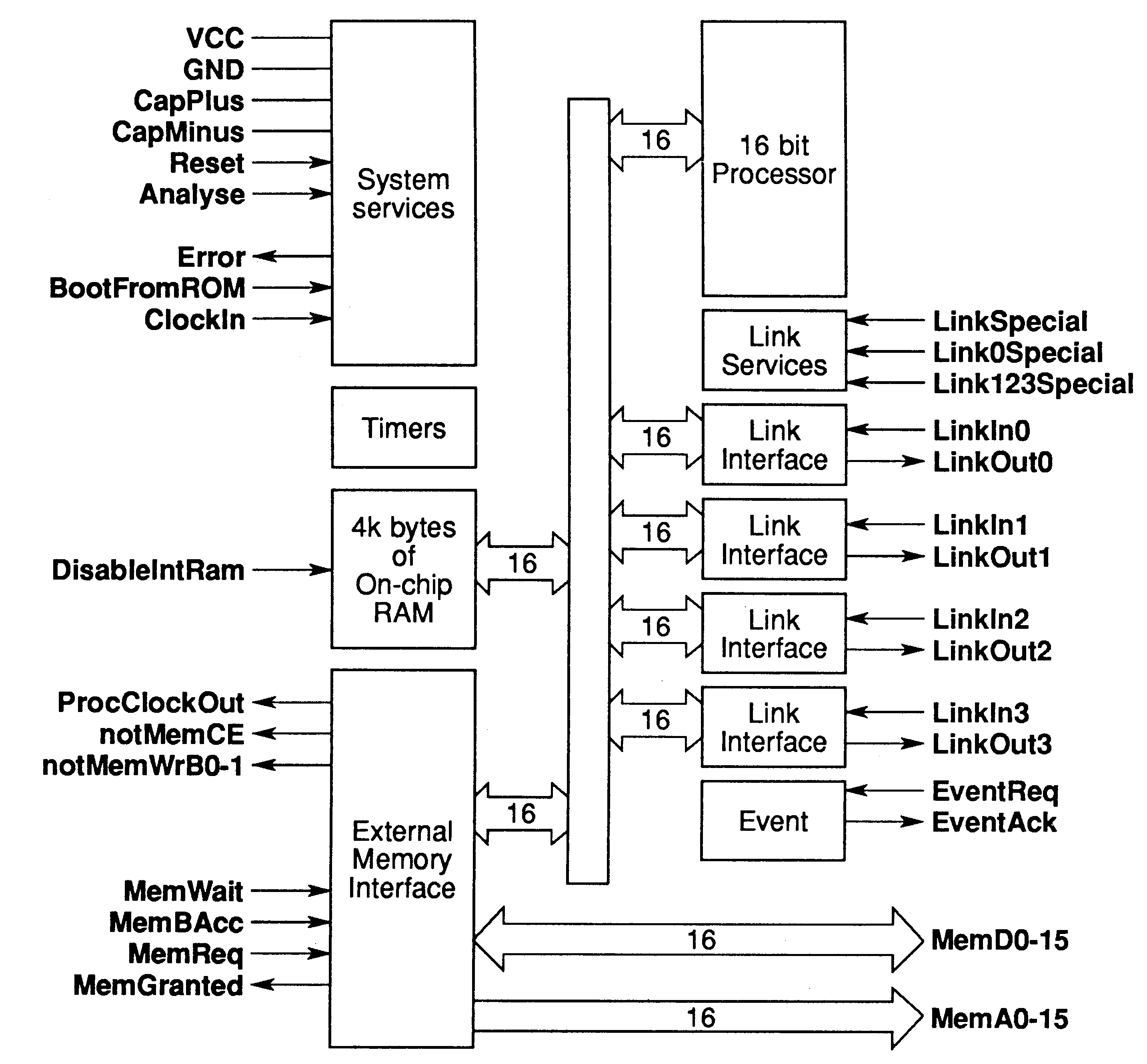
An important application area for transputers is as embedded controllers. This technical note describes the features that make transputers particularly useful as controller chips. The emphasis is on a new 16 bit device, the IMS T222.
A block diagram of the IMS T222 is shown in Figure 1
Transputers are designed to be easy to use. A transputer requires only a 5 V supply and a 5 MHz clock in order to function as a usable computer. Minimal external ‘glue’ logic is required to build a system with additional external memory or peripherals - typically 10 times less than other processors for a comparable system.
Transputers can be connected together via the serial links. Each link uses only two wires and connects two transputers together. This allows IMS T222’s to communicate at data rates up to 20 Mbits/second. The links are controlled by autonomous DMA engines and so can transfer data independently of, and concurrently with, the processor.
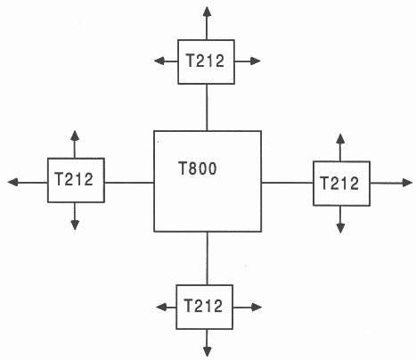
The links allow transputers to be used to build distributed systems, where processors are local to the equipment they control but can transfer information via the links. They can also be used to construct highly parallel systems for tasks requiring large amounts of computing power. Alternatively the links allow some processing to be farmed out to a second processor. For example several IMS T222’s could share a single IMS T800 acting as a floating point co-processor (see Figure 2).
Transputers provide support, in hardware and microcode, for concurrency and communication. There is a microcoded scheduler which allows any number of concurrently executing processes to share the processor’s time. The scheduler supports two levels of priority. Low priority processes are executed whenever there are no high priority processes which are ready to execute. A high priority process runs until it has to wait for a communication or timer input, or until it has completed processing. When a high priority process becomes ready it can interrupt any currently executing low priority process. Processes which are descheduled, waiting for a communication or delayed input, do not consume any processor time.
The IMS T222 has a typical context switch time of 600 ns and a maximum interrupt latency of 53 processor cycles (approximately 22μs).
Transputers include a large degree of on-chip concurrency, e.g. an IMS T800 can communicate through 8 link channels, perform integer processing and floating point arithmetic all at the same time. Writes to external memory can overlap with processing or accesses to on-chip RAM.
The IMS T222 also consumes little power; a system with external memory will consume approximately 100 mA. When the processor and links are idle, or if there is no external memory, then the current drawn will be only 80 mA. Although not guaranteed by INMOS, experiment has shown that the supply voltage can safely be reduced to 3 Volts when the processor is idle. This further reduces the power consumption to about 60 mW. Active power consumption can also be approximately halved by running the transputer with a 2.5 MHz input clock. Compatibility with other transputers is maintained if the links are set to run at ’20 Mbits/second’ when they will actually work at the standard link speed of 10 Mbits/second.
Transputers can be bootstrapped from ROM or from a message received down one of the links. This makes it possible to build a multiprocessor system with only a single ROM to bootstrap all the transputers. The IMS T222 has a simple, 16 bit wide, non-multiplexed memory interface. This allows access to up to 64 Kbytes of memory via separate address and data buses. The data bus can be configured for either 8 bit or 16 bit wide memory, allowing the use of a single bank of byte-wide memory. Both word-wide and byte-wide accesses can be mixed in a single memory system.
Compilers are available to program transputers in a range of high level languages. INMOS supplies compilers for C, Fortran, Pascal and occam 2. Occam was designed to allow simple and efficient exploitation of the transputers unique features. Occam is used in this note to provide programming examples to avoid the need for assembly language or a special dialect of a standard language.
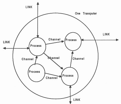
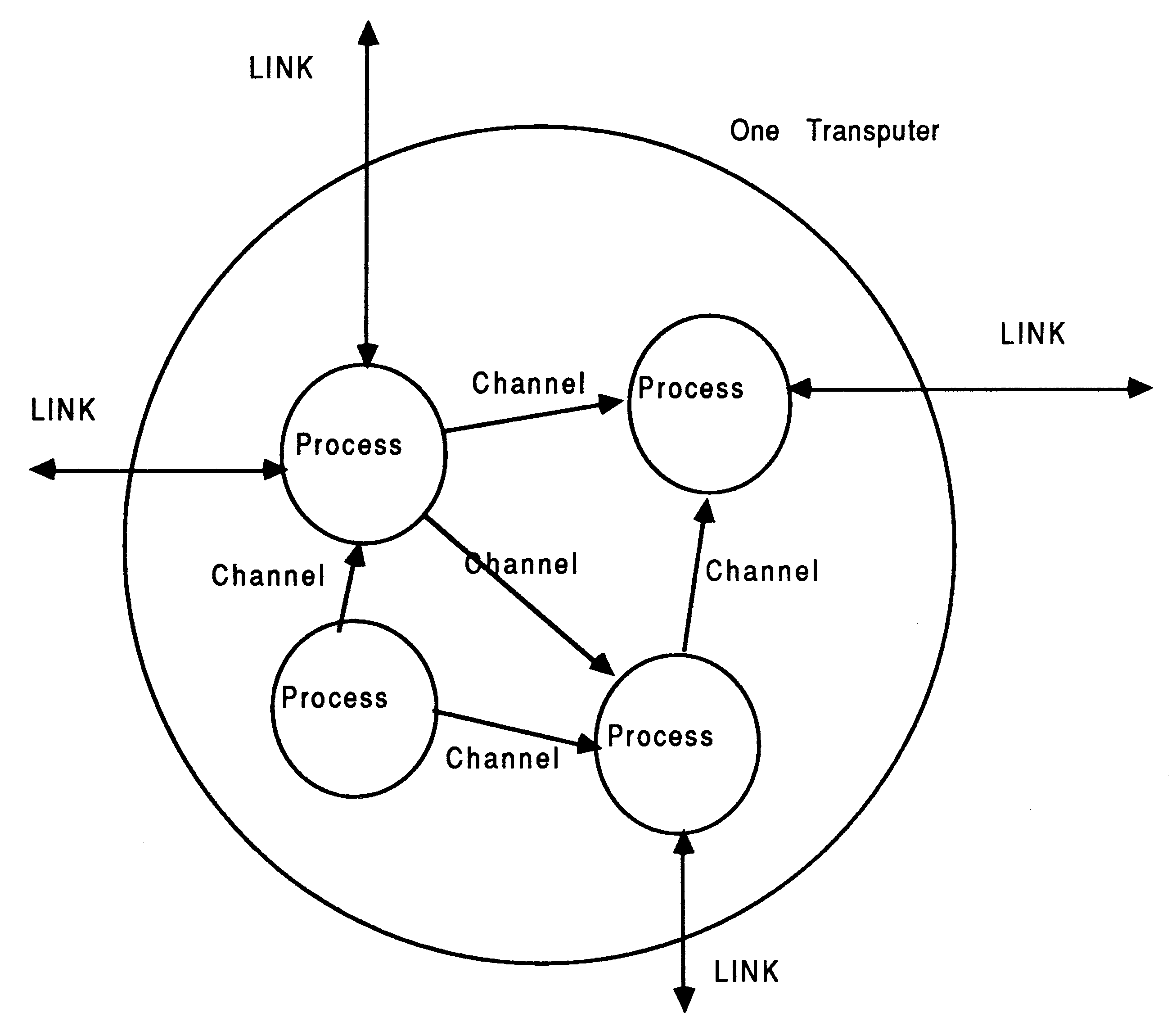
Occam describes systems in terms of concurrently executing, communicating processes (see Figure 3). This model is probably more readily assimilated by hardware engineers than programmers who have been brought up in a sequential programming environment. The ability to have multiple processes active at the same time removes much of the need for interrupt handlers and real-time kernels required with other processors. Because there is microcode and hardware support for concurrency and communication, structuring programs in this way is as efficient as traditional procedure/subroutine approaches.
The processor in the IMS T222 typically executes 10 million instructions per second at 20 MHz. Many instructions are one byte long and execute in a single cycle. There is a fast, unchecked multiply instruction; this is designed primarily for array subscript calculations but can be used for normal maths if overflow checking is not required. There are also instructions to support multiple length arithmetic.
A number of standard benchmarks have been run on the IMS T222 giving the following performance figures:
| Benchmark | Performance |
| Whetstone | 180K Whetstones/sec |
| Dhrystone | 8711 Dhrystones/sec |
| Savage | 21.9 seconds (abs. err. 1.2E-9) |
The IMS T222 is very fast at floating point arithmetic (in the Whetstone benchmark it performs slightly faster than the Intel 8086/7 combination and about ten times faster than a 68000).
Interrupts are the usual way of handling devices that require infrequent but fast servicing.
The transputer has a microcoded scheduler which enables any number of concurrent processes to be executed together, sharing processor time. Processes which are descheduled, waiting for a communication or delayed input, do not consume any processor time. The scheduler supports two levels of priority.
The latency between the time a process becomes ready to execute and the time it begins processing depends on the priority at which it is executing. Low priority processes are executed whenever there are no high priority processes which are ready to execute. A high priority process runs until it has to wait for a communication or timer input, or until it has completed processing.
Low priority tasks are periodically timesliced to provide an even distribution of processor time between computationally intensive processes. If there are n low priority processes then the maximum latency is 2n − 2 timeslice periods. The latency will generally be much less than this as processes are usually descheduled for communication or by a delayed input before the end of their timeslice. The timeslice period is approximately 1 ms.
High priority processes run whenever they are able to, interrupting any currently executing low priority process if necessary.
PRI PAR
... interrupt handler ... background tasks |
There are several sources of interrupt on the transputer, these can be internal or external. Internal sources are the completion of a channel communication or a delayed timer input becoming ready. External interrupt sources are the communication links and the event input pin; these are all mapped onto communication channels. As a transputer can support any number of processes communicating on channels and waiting on timers, there can be a very large number of interrupt sources.
If a high priority process is scheduled, and no other high priority processes are running, then the interrupt latency is typically 19 processor cycles (0.95 μs with a 20 MHz processor clock). The maximum interrupt latency is 53 cycles (2.65 μs).
These times indicate that the IMS T222 can handle hundreds of thousands of interrupts per second, even while engaged in computationally intensive tasks involving floating point calculations. For example, if the background tasks is the Whetstone benchmark and the timer is used as a source of interrupts then the following figures are obtained:
| Interrupts/sec | Whetstones/sec |
| 0 | 180,000 |
| 10,000 | 165,000 |
| 50,000 | 116,000 |
| 100,000 | 74,000 |
| 250,000 | 2,500 |
The interrupt handling routine in this test was an empty loop, so what is being measured is the overhead of handling an interrupt. If the interrupt handler performs some useful work then time taken for that is simply taken from the total CPU time available - i.e. the time available for the background task will be reduced in direct proportion to the time used by the interrupt handler.
All sources of interrupts are handled very simply and regularly on the transputer. This is very important as interrupts handlers are notoriously difficult to write and debug; they are usually only supported by programming in assembler and this is often very difficult to integrate with other code written in a high level language. All interrupts are seen by the transputer programmer as communications or timer waits. So, the high piority process in the previous example can be scheduled by a communication on a channel:
PRI PAR
-- interrupt handler SEQ interrupt ? x ... service interrupt ... background tasks |
This communication can be on an internal channel from another process on the same transputer, a link from another processor or a transition on the EventReq pin. The difference is simply the address of the communication channel. So, if the example above were preceded by PLACE interrupt AT 8, the interrupt source would be the EventReq pin (8 is the address of the event channel logic). Without an explicit placement the source of interrupts will be the process at the other end of the channel interrupt.
So, code which handles an external event, for example, can easily be tested by using a normal communication channel in place of the event channel. When the behaviour of that process has been tested then it is only necessary to place the channel at the address of the event input and the process becomes an event handler.
The serial communication links provide a simple and fast means of transferring information between transputers. Each link requires only two wires and provides bidirectional communication (i.e. two occam channels) between two transputers. The links are controlled by their own DMA engines which can each operate concurrently with, and independently of, the processor. This allows the links to transfer data at the same time as the processor is executing another process; when the communication completes the process which initiated it will be rescheduled.
The INMOS standard link speed is 10 Mbits/second, but the links on the IMS T222 support data rates up to 20 Mbits/second. This gives a bandwidth on each link of 1.48 Mbytes/second unidirectionally or 2.05 Mbytes/second bidirectionally.
The charter for the study was to demonstrate the suitability of the 16-bit members of the transputer family, the IMS T212, and the IMS M212, for controller applications. There were two vehicles for the study. The main one was a video cassette recorder (VCR) controller, and a subsidiary was an engine controller for a car. The previous generation VCR was to be taken as a basis, and its multi-chip control circuitry replaced with a transputer based board. On the engine controller, the mission was to allow much finer-grain control of the engine, and possibly to generate the control parameters on line, rather than using a lookup table approach as is necessary using slower controllers. 1
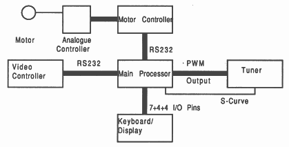
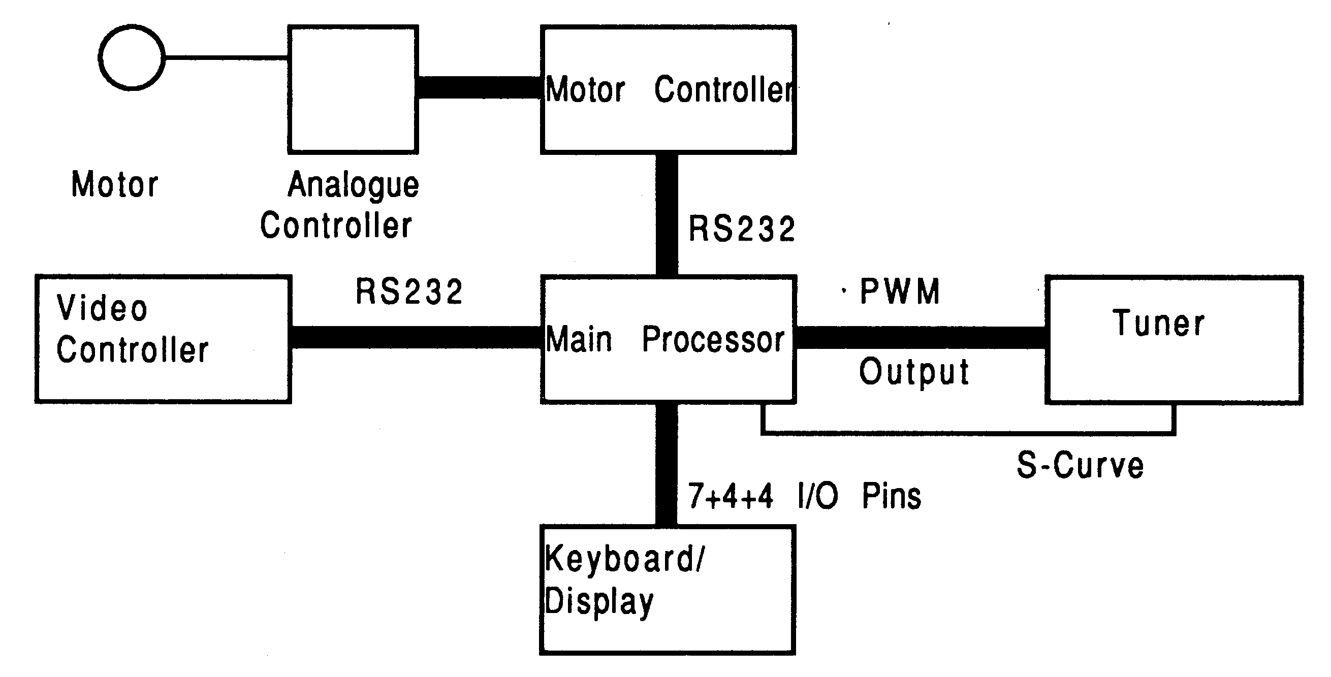
The original VCR used a low performance 8-bit micro-controller, and several intelligent peripherals. The main functions were keyboard and display control, including time of day if the display was idle, channel selection and control of the UHF tuner. In addition, via peripheral chips, it controlled the locking of the drum motor to incoming video sync signals, and the display on the screen, superimposed on off-air video, of programming information such as channel, start time, end time, for future programmes.
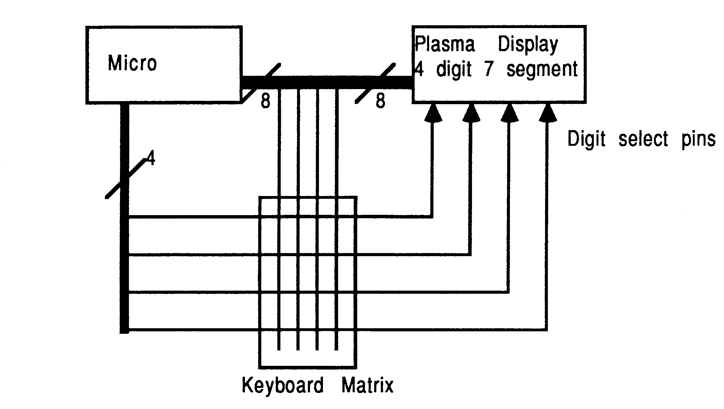
The keyboard was a matrix of simple contact switches arranged 4 x 4. The display was a plasma display requiring a 7 bit segment pattern and one strobe signal for each digit.
In order to economise on IO pins, the four drive signals to the keyboard columns re-used four of the digit strobes. Four further pins detected if a key in any of the four rows was depressed.
In another version, an LCD display was used with its own controller chip (Hitachi’s 44780 or LCD II). This required a four bit bus, an enable, a write line and a register select (command/data). In this case, the same four bit bus is used to activate the keyboard matrix.
The UHF tuner is controlled by means of an analogue voltage applied to a varicap diode. The analogue voltage is generated by a pulse width modulator (PWM), varying the mark space ratio to achieve an accurate control voltage. In order to isolate analogue, digital and RF signals, the tuner hardware is designed to take a digital PWM signal, so that the ratio is taken of the well regulated 30 Volt supply within the tuner. The frequency to tune to is selected by the user as channel n, which is then fine tuned by feedback from the demodulator (the S curve). The original design had an integrated PWM circuit on the micro. It implemented a 14 bit accuracy, 7 bits every cycle, and a further 7 bits by inserting an extra bit-time every nth cycle, where n is the 7 bit value.
On a VCR, it is necessary to ensure that the helical scanning of the tape is achieved in synchronism with the incoming video signal, such that the changeover between heads on the drum occurs during the frame flyback time and no video is lost. In order to achieve this an optical or magnetic sensor on the drum generates a sync signal, and the speed of the motor must be altered in two modes, first to achieve the desired speed, then to maintain synchronism with the incoming video.
The previous generation of VCR displayed the programming information on the television screen on demand, about ten lines of about 30 characters giving day, date, time and program. This was achieved with a dedicated display chip. It was an aim of this project that the transputer take over this role. No frame store was available, so the three hundred or so characters had to be generated to the screen at video rate, about 300 ns per character pixel.
Although this part of the project was made obsolete by taking the function of all the peripheral chips into the transputer, one step in the project involved implementing RS232 style serial communications with the display controller and the motor controller. This was provided in hardware on the traditional microcontroller, but was implemented in software on the transputer.
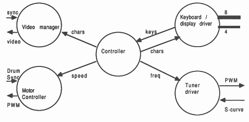
The transputer, even working alone, i.e. a single processor, supports concurrency. Thus it can run several intercommunicating tasks at the same time, with negligible inefficiency switching between them. This is achieved using a hardware scheduler, with no operating system or executive involved. The occam language allows such tasks to be described. Thus the function diagram of Fig 4 can be expressed in occam as:
CHAN OF msg1 control.to.display, control.to.motor:
CHAN OF msg2 keyboard.to.control: PAR ... controller ... video manager ... motor controller ... keyboard/display driver ... tuner |
This could be expressed pictorially as shown in Fig 6
Note the similarity between the software structure and the original hardware design.
Although separate functions, these are historically combined in order to save IO pins, even on calculators etc.
Two versions have been demonstrated, the plasma display and the LCD, the latter via a driver chip. The latter is most appropriate where the front panel display uses a preassembled display module that includes the driver.
The plasma display required a drive signal to each of seven commonned segments, and to a digit select pin, with special high voltage open drain transistors on these particular output pins. A pull-down resistor took the pins to -15 Volts when the transistor was off.
To drive the display, the following code was used:
BYTE segments, strobes, keys:
PLACE segments AT #4000: --port locations PLACE strobes AT #4001: PLACE keys AT #4002: --example addresses only SEQ ... init WHILE TRUE -- ie forever ALT clock ? AFTER next.update SEQ --*********HANDLE DISPLAY************* digit := (digit+l)\max.digits --REM makes it cycle round strobes := 0 --so that segment change --does not corrupt current char segments := seven.seg[chars[digit]] strobes := 1 << digit --least significant digit numbered 0 next.update := next.update PLUS time.per.char --*********READ KEYBOARD************** key.lines := keys --staticise by single read IF key.lines <> 0 IF (key.lines = old.key.lines[digit]) AND (NOT reported[digit]) -- debounce SEQ --lookup and transmit char to controller key.to.control ! key.table[digit][key.lines] reported[digit] := TRUE TRUE --ie otherwise SEQ old.key.lines[digit] := key.lines reported[digit] := TRUE TRUE SKIP --no auto-repeat supported --*************COMMAND from CONTROLLER*************** control.to.display ? chars[next] next :=( next + 1) REM max.chars --simple version, --controller does --scroll and blank |
The LCD display model was much simpler. Its controller provided all the display timing operations, so the refresh is not required. Instead, a timing operation is needed to feed the character received from the VCR control process. This simply puts the data on a 4 bit bus to the LCD, and raises and lowers the enable line with another pin. It must still be done within this ALT statement, as the keyboard handler shares the same pins.
Thus the line starting segments is omitted above, and the COMMAND from CONTROLLER section becomes:
control.to.display ? char
BYTE bus: --memory mapped io PLACE bus AT #4010: --example only SEQ clock ? now bus := char /\ #F0 --top four bits on D4 thru D7 now := now PLUS set.up.time --modulo arithmetic clock ? AFTER now bus := (char /\ #F0) \/ enable.bit now := now PLUS write.time clock ? AFTER now bus := char /\ #F0 now := now PLUS hold.time clock ? AFTER now char := (char /\ #F) << 4 --bottom 4 bits on D4 thru D7 ... pin wiggling as above for second nibble |
Discrete channels were chosen by the user numerically. From this the micro was required to look up the necessary control voltage required by the tuner from a table, apply it to the tuner, and then fine tune it by monitoring the S-curve of the demodulator. For the transputer version the S-curve was thresholded into separate tune-up and tune-down pins.
Different countries have different standards for tuning. The version chosen was that the user should select a channel number, then hand tune this up or down to the station he wished, then press a ”store” button, and from then on whenever he selected that channel number, he would get that same station. An auto-search version would actually have been easier to implement, as the processor can track the S-curve to detect each station.
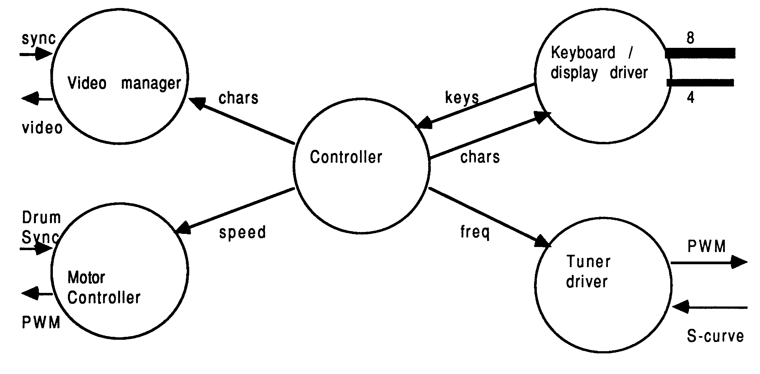
The program consists of two parallel processes, one maintaining the tuning database, at the rate that user keystrokes can be input, the other maintaining the PWM analogue output. In this example, ASCII control codes were used, with a number (0-9) selecting a channel, whose lookup-table value would be passed to the PWM. Codes ’U’ and ’D’ were used to tune the channel up and down, and code ’S’ to store the value permanently.
PRI PAR
... tuner manager/PWM ... channel manager |
The tuner being at high priority minimises jitter on the output waveform as the job is scheduled immediately. It also gives it access to the 1 microsecond clock.
The channel manager becomes
... decls
SEQ ... init WHILE TRUE --ie forever SEQ control.to.tuner ? control.code IF (control.code >= ’0’) AND (control.code <= ’9’) SEQ channel := control.code - (INT ’0’) pwm.value := chans[channel] tuner.to.pwm ! pwm.value control.code = ’U’ SEQ pwm.value := pwm.value + step.size tuner.to.pwm ! pwm value control.code = ’D’ SEQ pwm.value := pwm.value - step.size tuner.to.pwm ! pwm value control.code = ’S’ chans[channel] := pwm.value TRUE --all other cases SKIP --ignore |
Note that the demonstration version written actually had coarse and fine tune, i.e. different stepsizes, depending whether the control code was upper or lower case, but this has been omitted for brevity.
The PWM program was written as a direct emulation of the old hardware, i.e. 14 bits divided 7 and 7. If written for production, it would of course use 16 bits, 8 + 8, as being much more suitable for software implementation.
The algorithm used here allows semi-infinite accuracy over time, with jitter as allowed by the 2 microsecond timeslot specified. It is a discrete differential analysis (DDA) algorithm, where every step performs an addition of the accumulated error, and when the error reaches half a unit, the integer count is incremented and the error decremented by a normalised unity (in this case 127).
The time domain is divided into three phases.The first is the off time, defined by the upper 7 bits of the 14 bit pwm value. Next is the on time, defined by the remaining time in the nominally constant cycle time. The third phase is the extra on time, added periodically as needed to the cycle length, as the value in the lower 7 bits of the pwm value accumulate. Note that the DDA approach means that there is no step change, eg from one insertion every 5 cycles to one every 6. It would go from 5,5,5,5,5 to 5,5,5,6,5 for example, to achieve very fine tuning. Note that the DDA approach does not require any multiplication or division.
The reason, in the original hardware and this software, for using two halfwidth controls is to minimise the filtering required to convert the signal to DC. This method yields a period of 512 microseconds, i.e. 2 KHz, which is easily low pass filtered. If a single 14 bit value were used, the period would be 32 milliseconds, i.e. 30 Hertz, very inconvenient, and any filtering that could handle it would also prevent fast tuning across the band.
The pwm part of the program becomes:
... decls -- initialisation
SEQ clock ? start pin := 0 running := TRUE pwm.value := 63 << 7 -- real program start upper := pwm.value >> 7 lower := pwm.value /\ #7F error := 0 extra := 0 WHILE running ALT clock ? AFTER start PLUS extra SEQ pin := 0 clock ? AFTER start PLUS ((upper << 1) + 1 ) ie 2 us units pin := 1 start := start PLUS full.period error := error + (norm.one - lower) --minus to reverse IF --as extra is on time error >= norm.half --while upper is offtime SEQ error := error - norm.one --DDA extra := 2 --microseconds sync := 1 --to drive oscilloscope TRUE --for demo SEQ extra := 0 sync := 0 to.pwm ? pwm.value --retune request IF pwm.value < 0 running := FALSE --stop demo TRUE SEQ upper := pwm.value >> 7 --offtime lower := pwm.value /\ #7F --accumulate for extra |
The motor control is required to keep the head drum of the VCR in synchronisation with incoming video. To do this the frame sync signal, and that from a sensor on the drum are fed to the transputer as two separate input bits, and also fed, ORed together, to the event pin of the transputer.
For the transputer based version, it is arranged that the drum signal is synchronous with, but not in phase with the video, so that the two high priority interrupts do not occur simultaneously. This is achieved by positioning the optical sensor appropriately.
The transputer timestamps the two signals, aiming to keep them the correct number of microseconds apart.
The first task, however, is to accelerate the drum to the correct speed. This is achieved by timing the drum sync signals, and sending values to a PWM as described above, which after an analogue amplifier, controls the DC motor. Note that the version below is a first order filter and will overshoot and ring due to the mass of the motor and drum. It is deemed accurate enough after it has been sampled as correct sufficient times. The first few ”correct” samples will be transitions sampled during the ringing. The number required must ensure that the speed is within limits for a defined interval. A more sophisticated version would have several stepsizes depending on the magnitude of the error, and could then be critically damped.
The second task is then to track the relative phase of the two signals, by a very similar algorithm.
... decls
SEQ ... init WHILE accelerating SEQ drum.sync ? any clock ? drum.time.2 VAL period IS (drum.time.2 MINUS drum.time.1) IF period > max.period motor.power := motor.power + step.size period < min.period motor.power := motor.power - step.size TRUE SEQ accurate := accurate + 1 IF accurate > enough accelerating := FALSE TRUE SKIP drum.time.1 := drum.time.2 to.pwm ! motor.power WHILE tracking SEQ PAR SEQ drum.sync ? any clock ? drum.time SEQ video.sync ? any clock ? video.time IF (drum.time MINUS video.time) < min.phase motor.power := motor.power + tiny.step (drum.time MINUS video.time) > max.phase motor.power := motor.power - tiny.step TRUE SKIP to.pwm ! motor.power --tell motor PRI ALT --accept command command ? tracking --to stop SKIP --if sent, TRUE & SKIP --otherwise proceed SKIP |
It can be seen that by taking a functional division approach to implementing the problem, each element of the program is simple to write and can be tested and or demonstrated separately, then used as a building block in the overall application. The inherent parallelism of the transputer’s hardware scheduler means that, within the limits of the amount of CPU time available, any number of this style of task can be run simultaneously, i.e. in parallel sharing the same microprocessor. The final test in situ is required to ensure that under real-life loads, any crisis times are met, but a well designed system will show trivial degradation under critical coincidences of CPU demand.
Another project that evaluated the transputers suitability for controller applications was an engine controller. The demands on CPU-time here are traditionally very high, due to the possibility of needing a spark every 2.5 milliseconds (based on a 4-stroke V8 engine at 6000rpm). There is little point in recalculating for every spark, however, if the engine rotation sensor only gives a signal once per revolution.
In addition to ignition control, there is fuel flow control. This again is traditionally calculated every injection time, which is overkill against a driver who has a time constant measured in seconds, an engine with a time constant in tenths of a second, and a vehicle mass with a time constant even slower than the driver. The advantage of the transputer in this application is that it is powerful enough to support the traditional sledgehammer approach, but it can also do that little extra calculation that allows a second order calculation (i.e. prediction, using acceleration), in order that the basic calculation need be done far less frequently.
The conventional approach is to use two micros, one responsible for the ignition system, the other for the fuel system. Input sensors are the accelerator position (i.e. demand), the engine position (one pulse per rev), and the engine load, normally given by a manifold vacuum sensor. The accelerator position can be omitted, as unsatisfied demand can be derived from the vacuum (or lack of). For fuel economy on overrun, a throttle sensor is preferred, and once provided, it simplifies implementation.
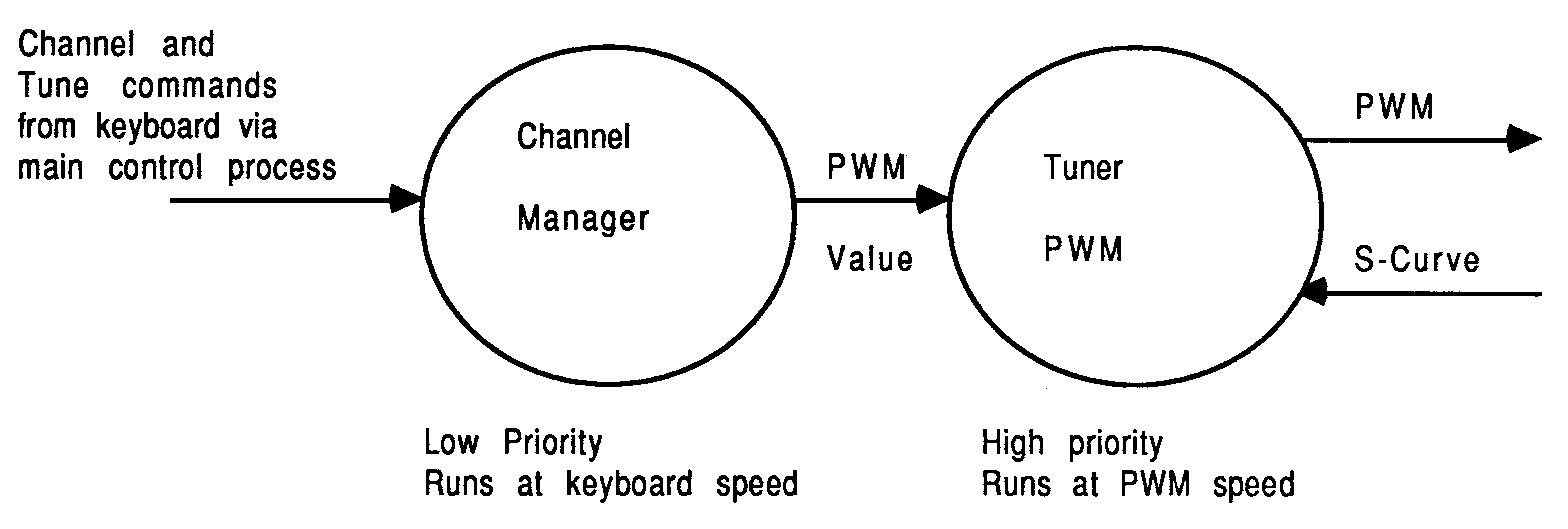
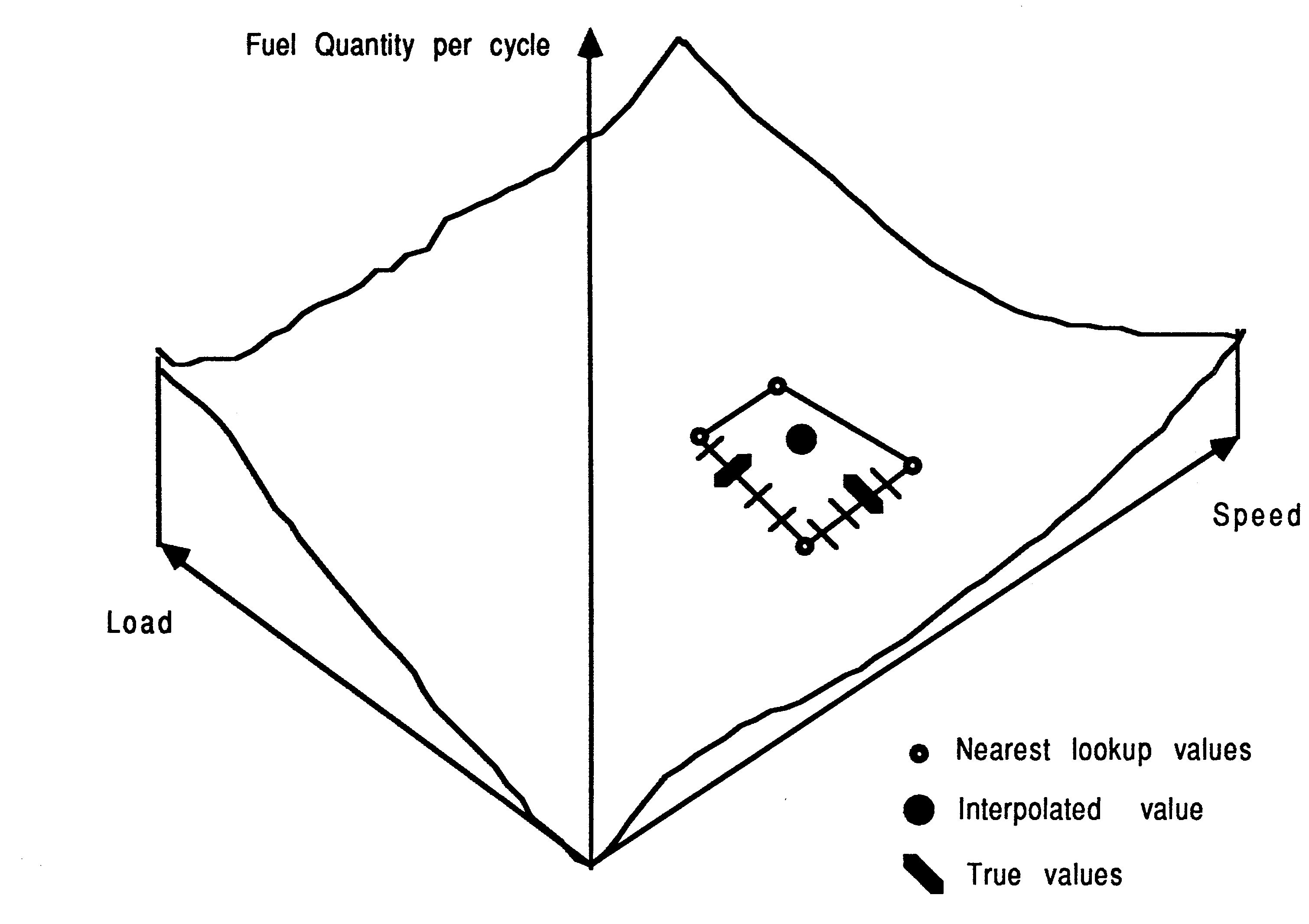
The traditional micro cannot, due to lack of processing power, support either calculation on a per cylinder basis, nor prediction. Thus the approach is to use the two micros, and to use a look-up table to get fuel quantity and ignition timing. However, this approach is limited by the size of ROM available, so results in a very poor granularity on the engine control.
Thus the approach used is to look up the four corners of the enclosing rectangle in the operating environment, and to use one of these as an initial approximation, then during the next few revolutions develop an interpolated, more accurate solution.
Result … poor acceleration, as only at constant speed is the tuning accurate.
On the transputer, it is possible to do either of the new methods, due to the order of magnitude speed increase over conventional microcontrollers.
The first method, the sledgehammer approach, is to calculate the timing and fuel quantity for every cylinder as necessary, from scratch.
The calculation required is to implement the following equation, where a,b,c,d,e,f are constant coefficients:
fuel := (a ∗ load + b ∗ load2 + c ∗ load3) ∗ (d ∗ revs + e ∗ revs2 + f ∗ revs3)
where conventional operator precedence is used. Additional brackets are needed for occam. An identical equation, with different coefficients is then used for ignition timing. This equation requires 11 multiplies and 4 adds, and executes (integer) in under 30 microseconds on a transputer. The second equation re-uses the squared and cubed terms, so needs only an additional 7 multiplies and four adds, so the entire calculation can be performed in a total of 50 microseconds, assuming preconditioned sensor inputs. With a required repetition rate of 2500 microseconds, there is plenty of time for signal conditioning.
Note that this calculation is again an emulation of the traditional method, and as such takes no note of engine history, i.e. accelerating needs richer mixture, for example. A complete approach, previously impossible due to the slow processors then available, would include terms relating to previous load, previous speed etc, and there would be simpler terms relating to engine temperature, inlet air temperature, humidity and pressure.
The second method is to calculate the expected timing/quantity and its rate of change, and to extrapolate forwards until the next complete recalculation. This means doing the above calculation twice to determine the gradients wrt time at the current acceleration rate, and then only one multiply and add for each of fuel and timing on a per spark basis.
The latter is preferable, as it allows the calculations to be as complex as desired, while the intervening engine revolutions are still accurately controlled. Because of the greater processor availability, the ignition and fuel can be controlled by one transputer, as well as the cruise control and other functions.
This report has shown the benefits of a very high performance microprocessor, and how its parallelism allows good I/O responsiveness at the same time as performing compute intensive tasks.
The applications section has shown a fully detailed implementation of a VCR controller, and a less detailed study of an engine controller. In both cases the transputer and occams total transparency in terms of time and parallelism, scheduling and communications mean that many tasks can be run at the same time. The 10 MIPS performance means that many hardware functions be brought into software, and the ease of programming means that groups of engineers unfamiliar with computers (i.e. VCR designers and engine designers) can rapidly achieve their desired goals.
[1] Transputer reference manual INMOS Limited Prentice Hall
ISBN 0-13-929001-X
[2] occam reference manual INMOS Limited Prentice Hall
ISBN 0-13-629312-3
[3] Extraordinary use of transputer links Technical Note 1 INMOS Limited
[4] Connecting INMOS links Technical Note 18 INMOS Limited
[5] Dual-inline transputer modules (TRAMS) Technical Note 29