|
|
| Designs and applications for the IMS C004 _____________________________________________________________________ |
| Glenn Hill September 1988 |
The IMS C004 is a 32-way crossbar switch that supports the INMOS link protocol. This article describes its functionality, discusses how it may be used as a design element to provide larger crossbar switches, and how it may be applied to configure large transputer networks. It also suggests how it can be used as a general purpose communication engine, and gives an occam description of a message routing exchange.
It includes a concise description of the IMS C004’s functionality using Hoare’s CSP notation as well as a CSP description of the message routing exchange.
The INMOS communication link is a new standard for system interconnection. It uses the capabilities of VLSI to offer simple, easy-to-use and cheap interconnections for computer systems. The serial link is a fundamental component of, and was developed as part of, the INMOS transputer architecture. The transputer is a single VLSI device with memory, processor and communications links for direct connection to other transputers. It is a programmable component which enables systems to be constructed from a collection of transputers that operate concurrently and communicate through links.
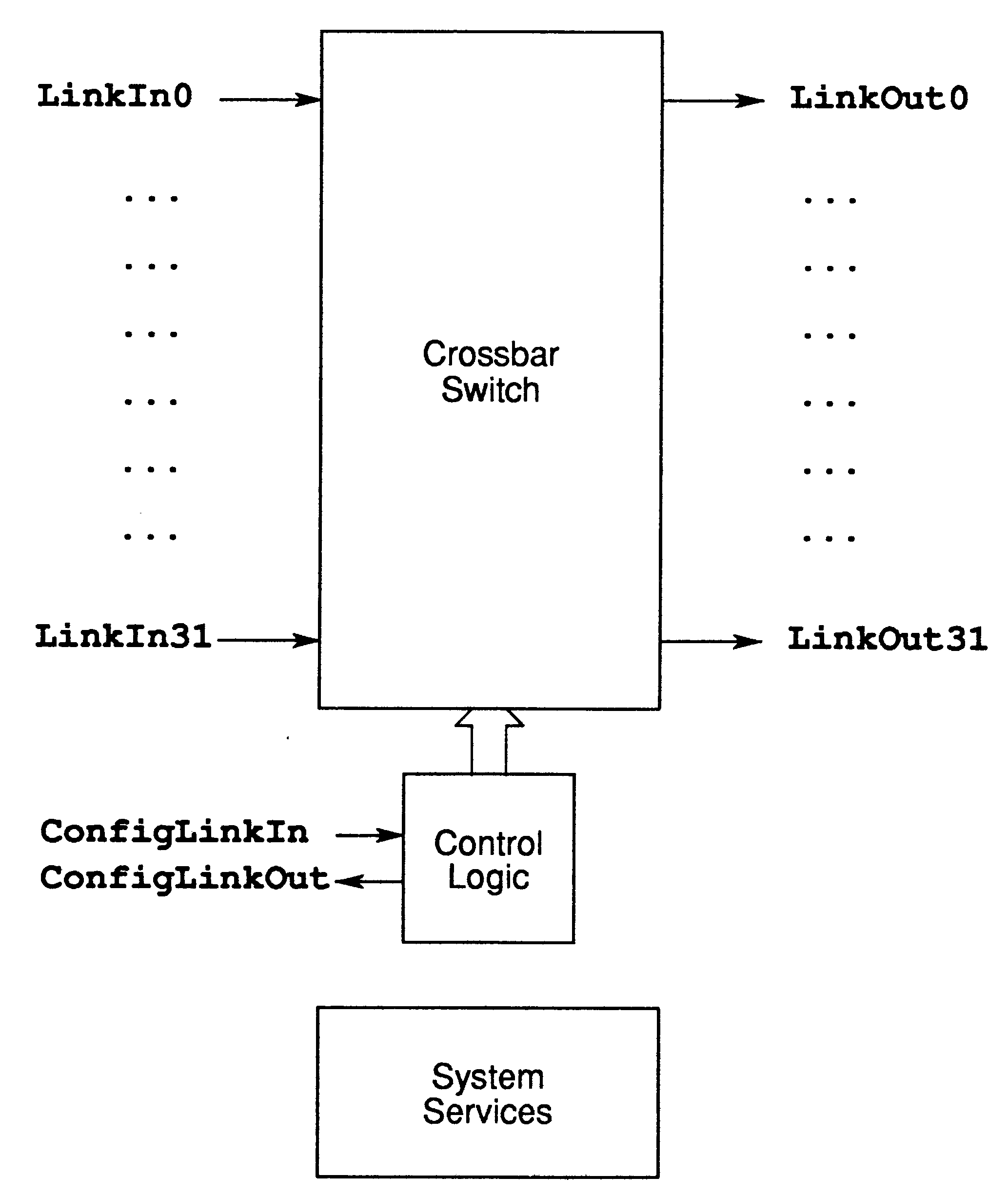
The IMS C004 programmable link switch provides a full crossbar switch between 32 link inputs and 32 link outputs. It will switch links running at standard transputer speeds (10 and 20 Mbits/sec). It introduces a 1.6 to 2 bit time delay on the signal.
The link switch can be cascaded to any depth without loss of signal integrity and it can be used to construct reconfigurable networks of arbitrary size.
The IMS C004 is programmed via a separate serial link called the configuration link.
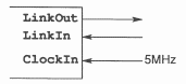
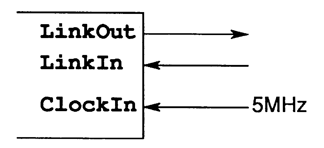
INMOS serial links are standard across all products in the transputer product range. All transputers will support a standard communications frequency of 10 Mbits/sec, regardless of processor performance. Thus transputers of different performance can be connected directly and future transputer systems will be able to communicate directly with those of today. Each link consists of a serial input and a serial output, both of which are used to carry data and link control information.
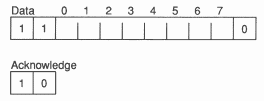
A message is transmitted as a sequence of bytes. After transmitting a data byte, the sender waits until an acknowledge has been received, signifying that the receiver is ready to receive another byte. The receiver can transmit an acknowledge as soon as it starts to receive a data byte, so that transmission can be continuous. This protocol provides handshake communication of each byte of data, ensuring that slow and fast transputers communicate reliably. When there is no activity on the links they remain at logic 0, GND potential.
A 5 MHz input clock is used, from which internal timings are generated. Link communication is not sensitive to clock phase. Thus communication can be achieved between independently clocked systems, provided that the communications frequency is within the specified tolerance.
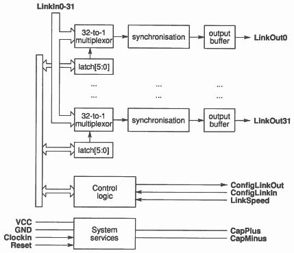
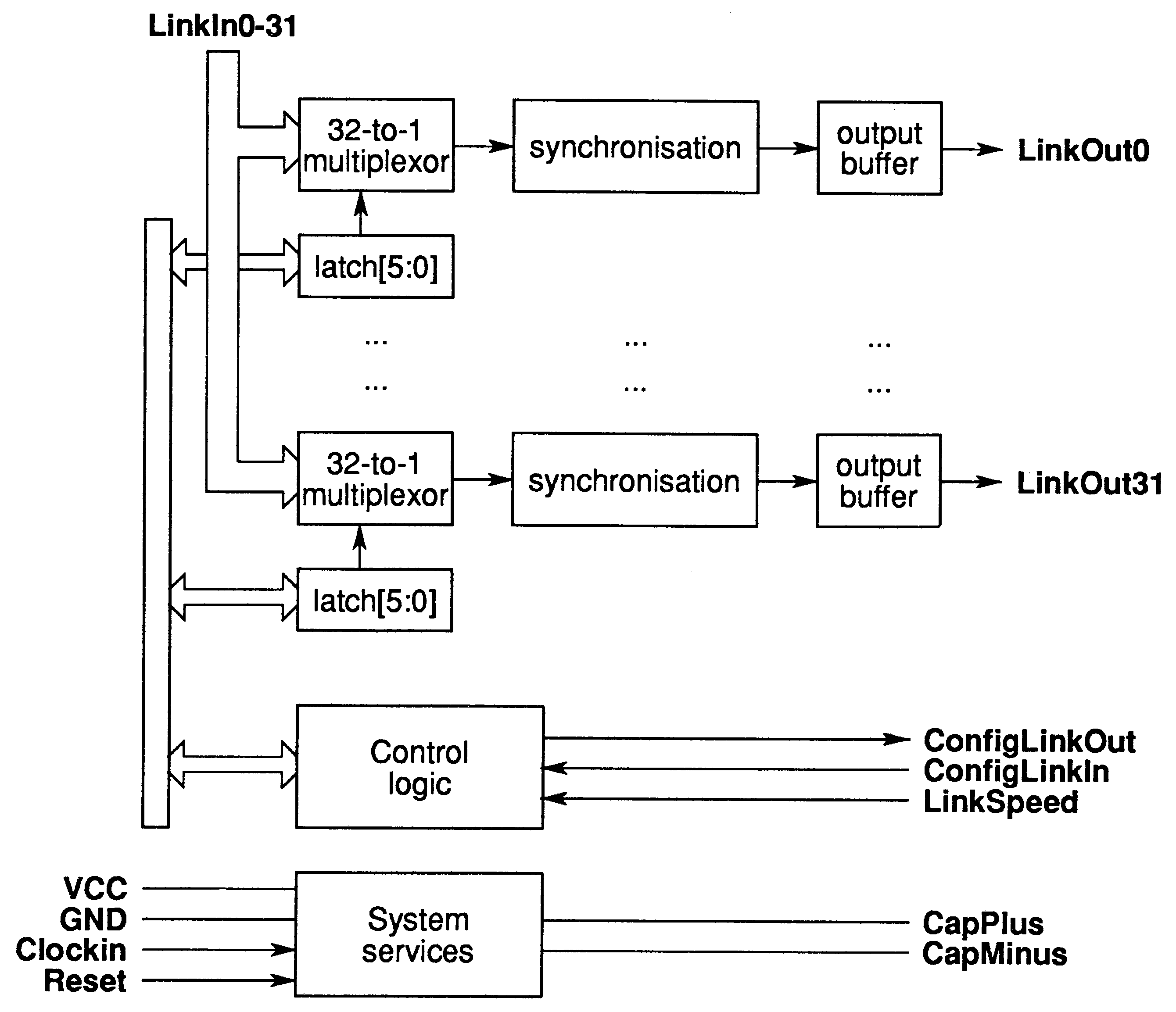
The IMS C004 is internally organised as a set of thirty two 32-to-1 multiplexers. Each multiplexer has associated with it a six bit latch, five bits of which select one input as the source of data for the corresponding output. The sixth bit is used to connect and disconnect the output. These latches can be read and written by messages sent on the configuration link via ConfigLinkIn and ConfigLinkOut.
The output of each multiplexer is synchronised with an internal high speed clock and regenerated at the output pad. This synchronisation introduces, on average, a 1.75 bit time delay on the signal. As the signal is not electrically degraded in passing through the switch, it is possible to form links through an arbitrary number of link switches.
Each input and output is identified by a number in the range 0 to 31. A configuration message consisting of one, two or three bytes is transmitted on the configuration link. The configuration messages sent to the switch on this link are shown in the table.
| Configuration Message | Function |
| [0] [input] [output] | Connects input to output. |
| [1] [link1] [link2] | Connects link1 to link2 by connecting the input of link1 to the output of link2 and the input of link2 to the output of link1. |
| [2] [output] | Enquires which input the output is connected to. The IMS C004 responds with the input. The most significant bit of this byte indicates whether the output is connected (bit set high) or disconnected (bit set low). |
| [3] | This command byte must be sent at the end of every configuration sequence which sets up a connection. The IMS C004 is then ready to accept data on the connected inputs. |
| [4] | Resets the switch. All outputs are disconnected and held low. This also happens when Reset is applied to the IMS C004. |
| [5] [output] | Output output is disconnected and held low. |
| [6] [link1] [link2] | Disconnects the output of link1 and the output of link2. |
This section gives a textual description of the functionality of the IMS C004. For a more formal description refer to section 7.
As detailed in section 2.2, there are seven commands that are used to set up the IMS C004. (N.B. In first revision of silicon, the two disconnect commands were not included.) These will be referred to in this document as
| ct.reset | (BYTE 4) |
| ct.input.output | (BYTE 0) |
| ct.link | (BYTE 1) |
| ct.enquire | (BYTE 2) |
| ct.disconnect.output | (BYTE 5) |
| ct.disconnect.link | (BYTE 6) |
| ct.setup | (BYTE 3) |
These commands are sent to the IMS C004 via the configuration link (ConfigLinkIn, ConfigLinkOut). These single byte commands may be followed by output identifiers, input identifiers or link identifiers as explained below, all of which should be in the range BYTE 0 .. BYTE 31.
After power on reset, the single byte command ct.reset should be executed. This ensures that all inputs are disabled (i.e. cannot receive data) and all outputs are inactive (i.e. are not connected to any input).
The ct.enquire byte should be followed by an output identifier.. The IMS C004 will then return, via the configuration link, an input identifier which represents the input to which that output is connected. This will be independent of whether or not that output is active. The most significant bit (bit 7) is set to 1 if the output is active. (N.B. In first revision of silicon this was not implemented.) Hence after a ct.reset command it is possible to find out to which input an output has been connected prior to the command. After a power on reset the input identifier returned after a ct.enquire command will be arbitrary.
The ct.input.output byte should be followed by an input identifier and an output identifier. This command enables the specified input, connects the specified output to that input and activates that output.
The ct.link byte should precede two link identifiers. This command is equivalent to two ct.input.output cornmands in which the identifiers are reversed; i.e.
ct.link link1 link2 = ct.input.output link1 link2;
ct.input.output link2 link1 |
The ct.disconnect.output byte should be followed by an output identifier. This command makes the specified output inactive.
The ct.disconnect.link byte should precede two link identifiers. This command is equivalent to two consecutive ct.disconnect.output commands; i.e.
ct.disconnect.link link1 link2 = ct.disconnect.output link1;
ct.disconnect.output link2 |
The ct.setup command is a single byte command that should be sent to the IMS C004 prior to using data links that have been redirected by the setup commands (ct.input.output or ct.link) to ensure that the IMS C004 has had enough time to be programmed correctly.
Since IMS C004’s are digital devices that effectively regenerate received data for transmission, they can be used as elements of larger switching networks without any signal degradation occurring when a link path is routed through several elements. The only drawback is that each IMS C004 can introduce a delay of up to 2 bits, and since each byte transfer requires a data and acknowledge packet to comply with the link protocol, the communication bandwidth is reduced by each IMS C004.
The IMS C004 is a 32-way crossbar switch. This doesn’t however restrict a designer to using a crossbar of this size. Large crossbars can be designed from smaller crossbar elements. This section introduces two possible design methods to achieve this, and describes how these methods can be used for cascading IMS C004s.
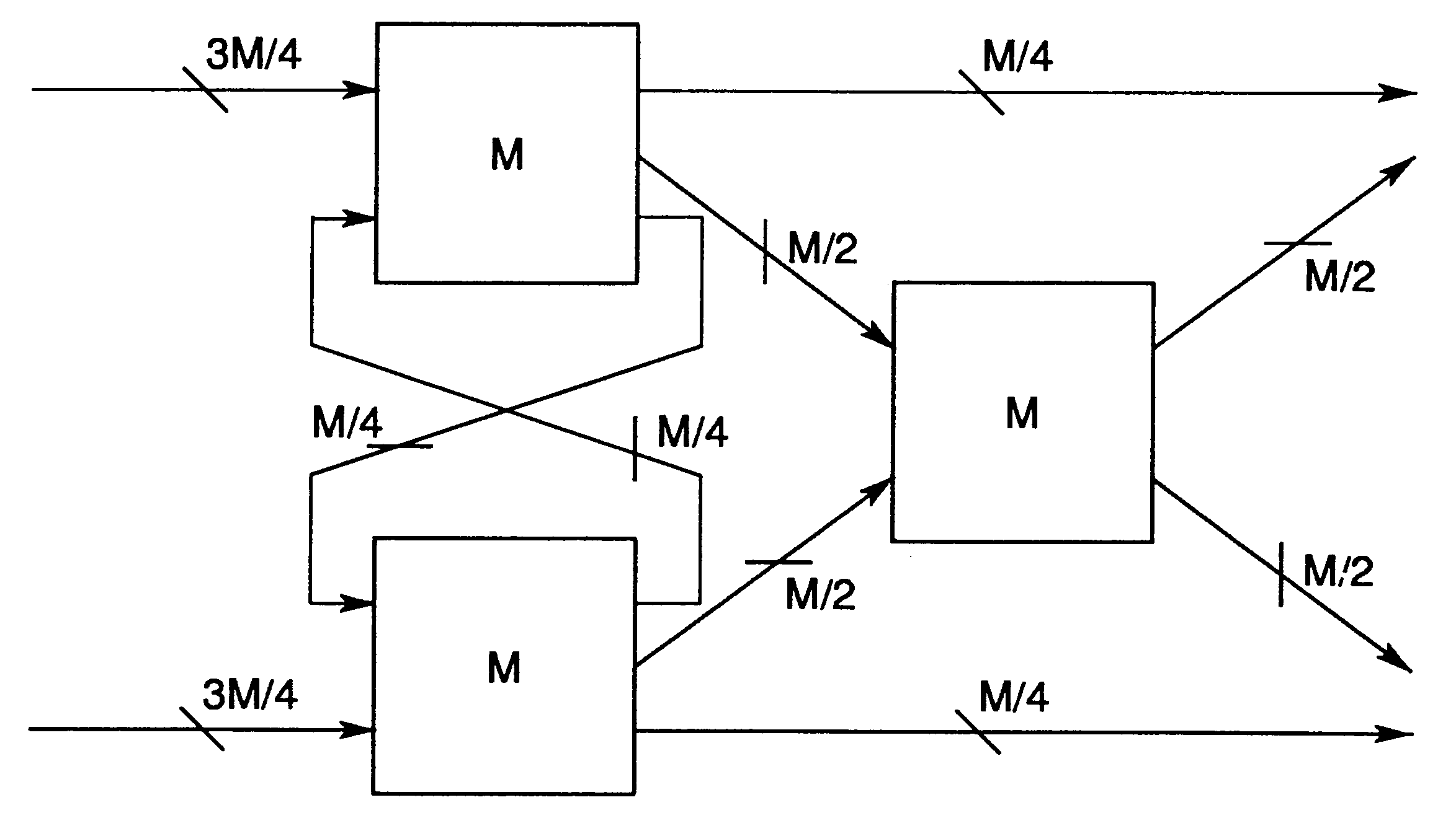
If a crossbar element of size M is available (M = 32 for an IMS C004) and a design requires a slightly larger crossbar, this can be achieved using three crossbars to produce a single crossbar of greater capacity. Figure 8 shows a special case where three identical crossbars (size M) are combined to produce a 50% larger crossbar (size 3M/2). The following text explains why this arrangement achieves the objective.
Assume that an N-way crossbar is required. That is, a circuit that can connect N inputs to N outputs in any permutation.
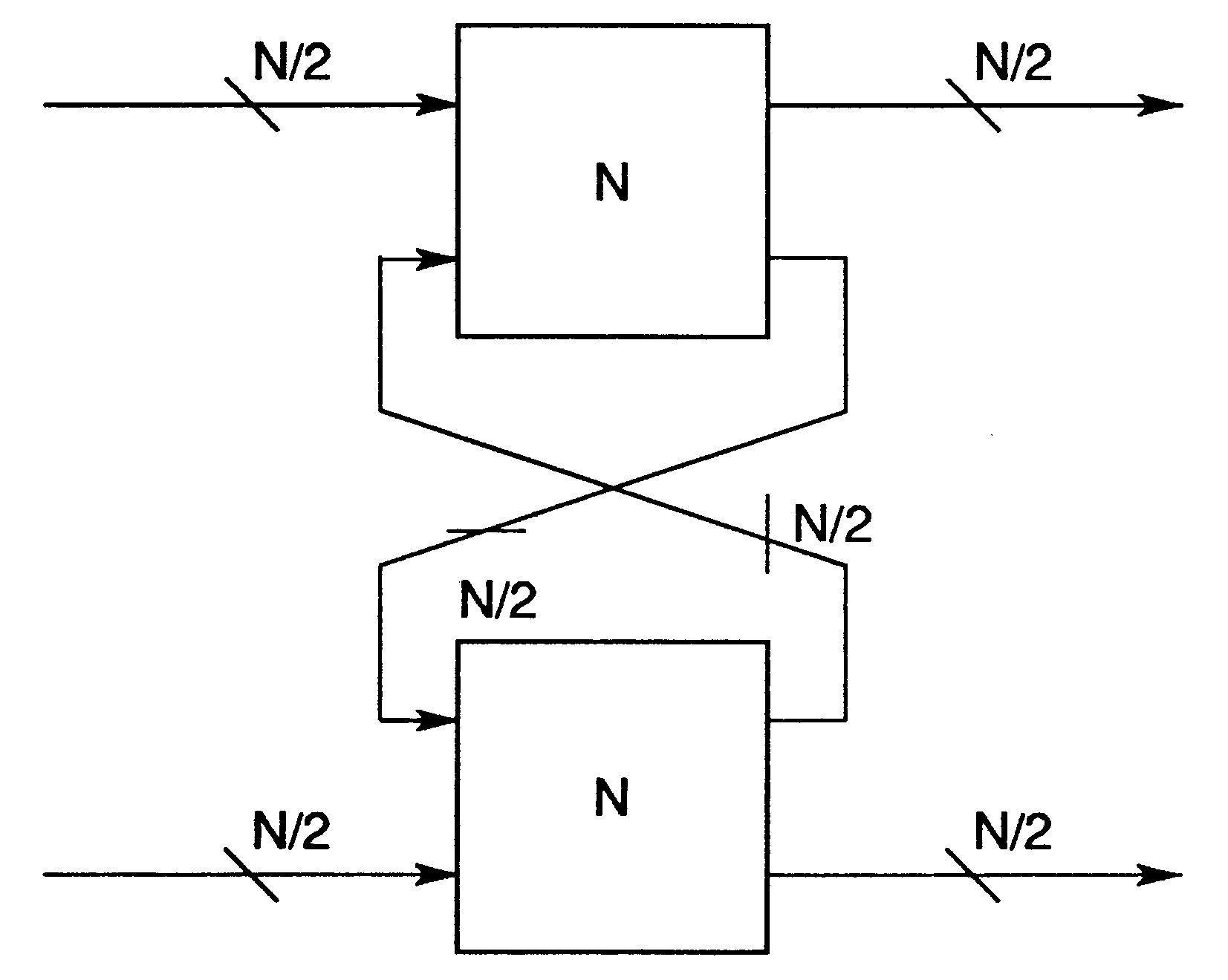
A trivial way of doing this is shown in figure 5. It is immediately obvious that this design has not achieved anything, since two N-way crossbars have been merged to derive a single N-way crossbar. Nevertheless, it is easy to see that the required circuit has been produced.
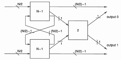
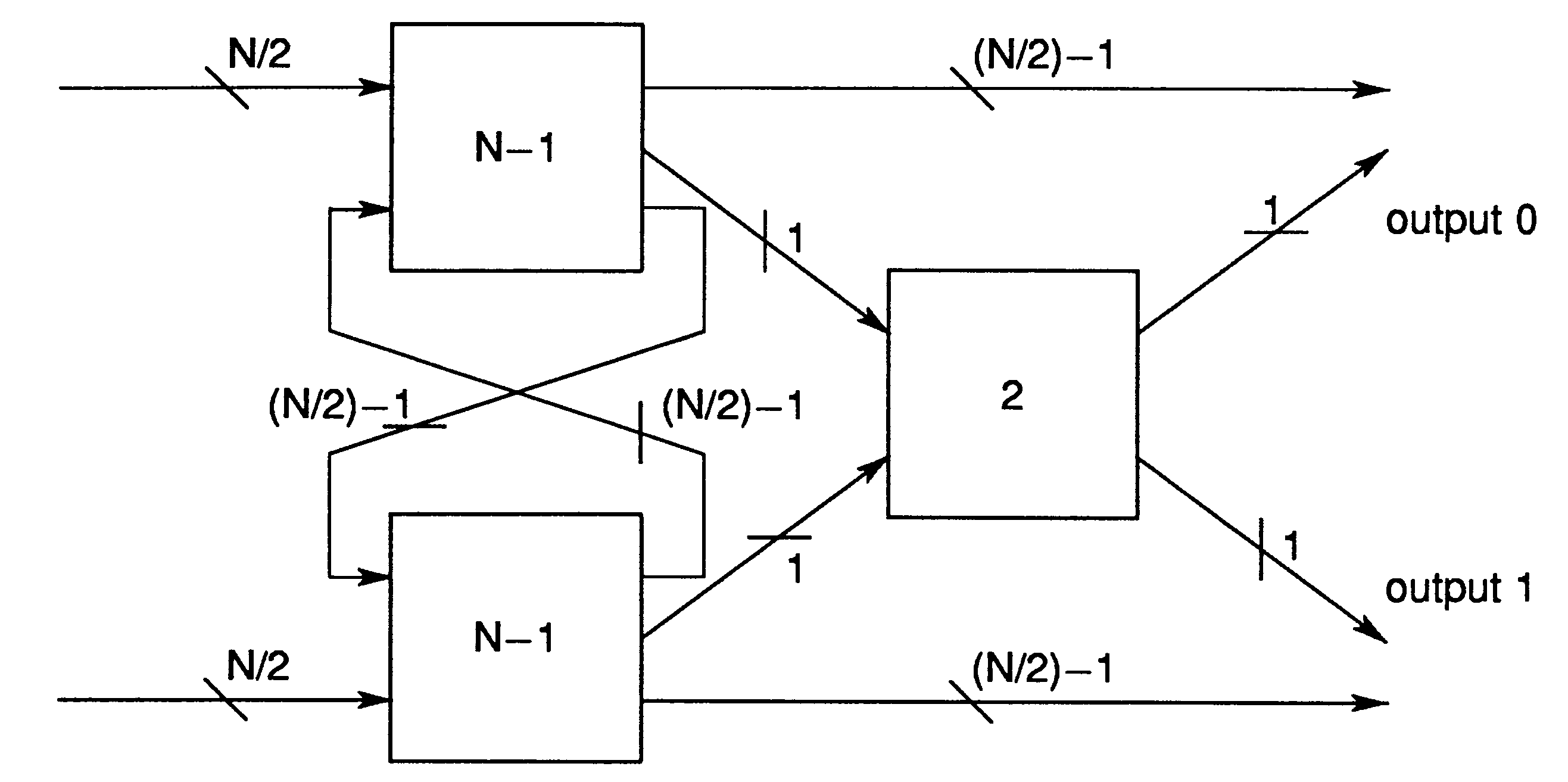
Another design that achieves our objective is shown in figure 6. Provided that we are happy with the design of figure 5, it is not very difficult to convince ourselves that this new design will also satisfy the requirement that any input can be connected to any output. If any input needs to be connected to either output 0 or output 1, then it must be routed via the 2-way crossbar. This still is not a particularly useful design, since there is a great deal of expense in producing a crossbar only one dimension larger than the two needed to implement it.
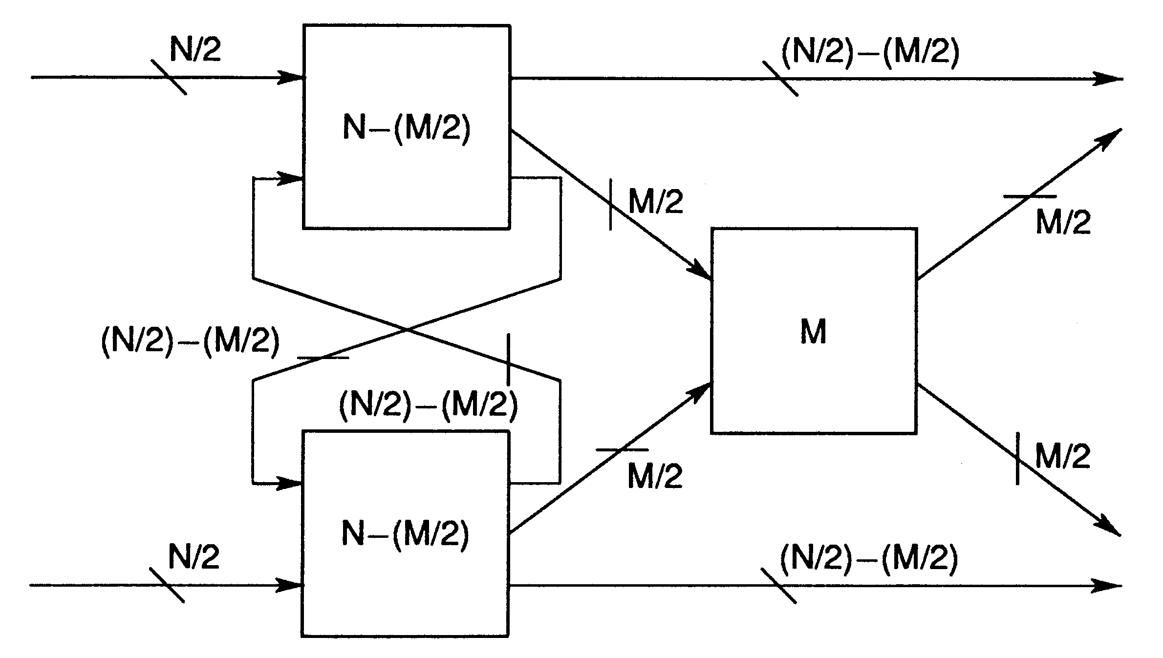
However, the concept is important because there is no reason why we cannot increase the size of the smaller crossbar, hence reducing the size of the larger ones to achieve the same result. Figure 7 shows the generalised design structure for combining three crossbars in this way to produce a larger crossbar. Now, if all three crossbars are of size M they combine to derive a crossbar of size 3M/2 (figure 8).
Three MS C004s can therefore be used to implement a 48-way crossbar.
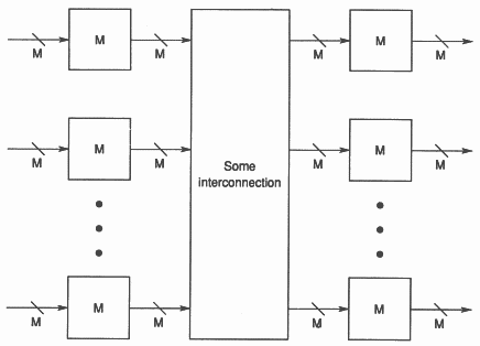
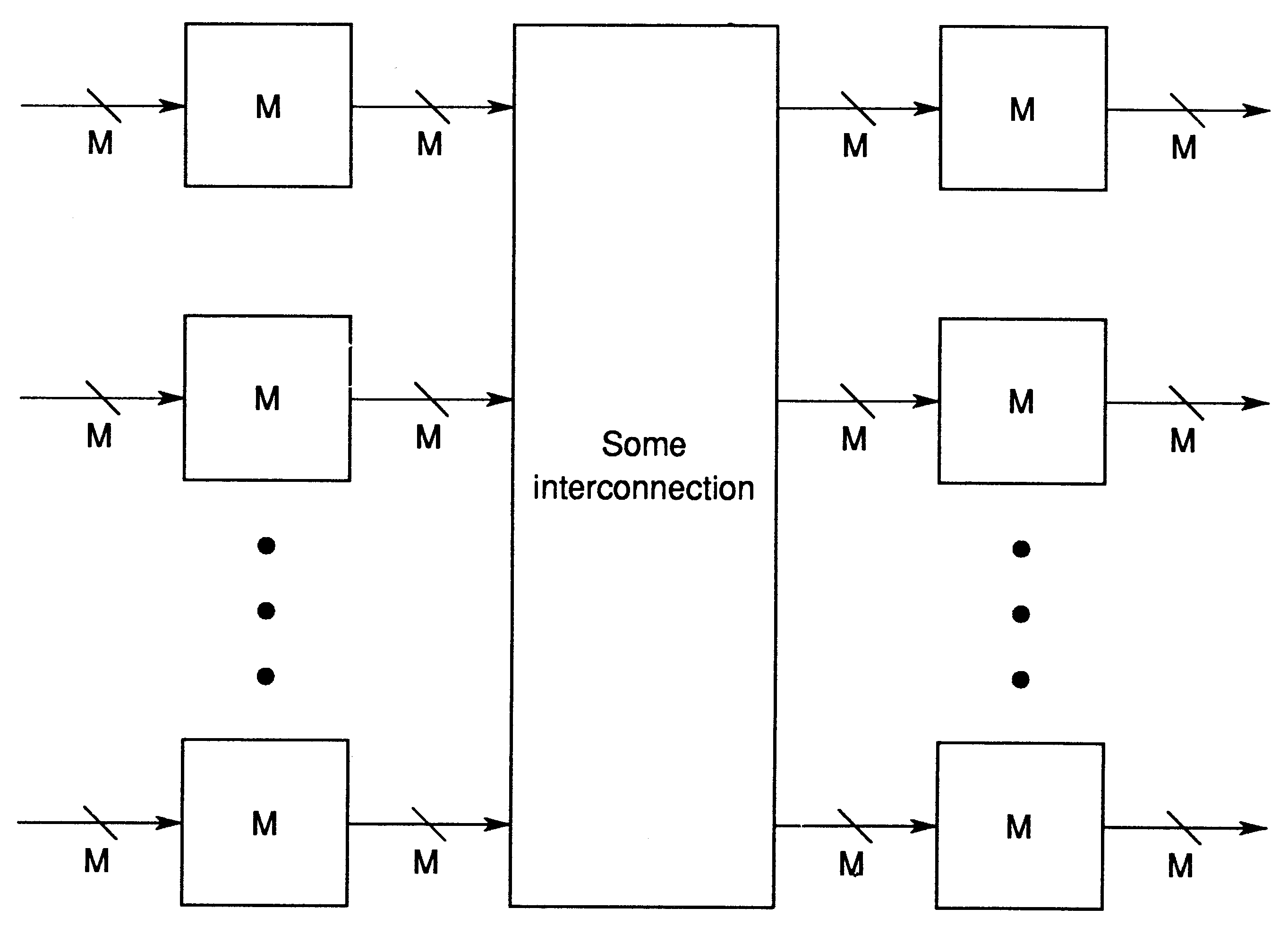
A large crossbar can be derived from smaller crossbar elements (M-way) as shown in figure 9. A first attempt at defining the unknown block might be a simple interconnection as shown in figure 10. But an obvious requirement for figure 9 is that there should be at least M paths between any input crossbar and output crossbar, which figure 10 does not satisfy.
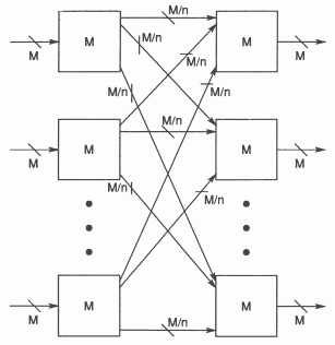
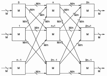
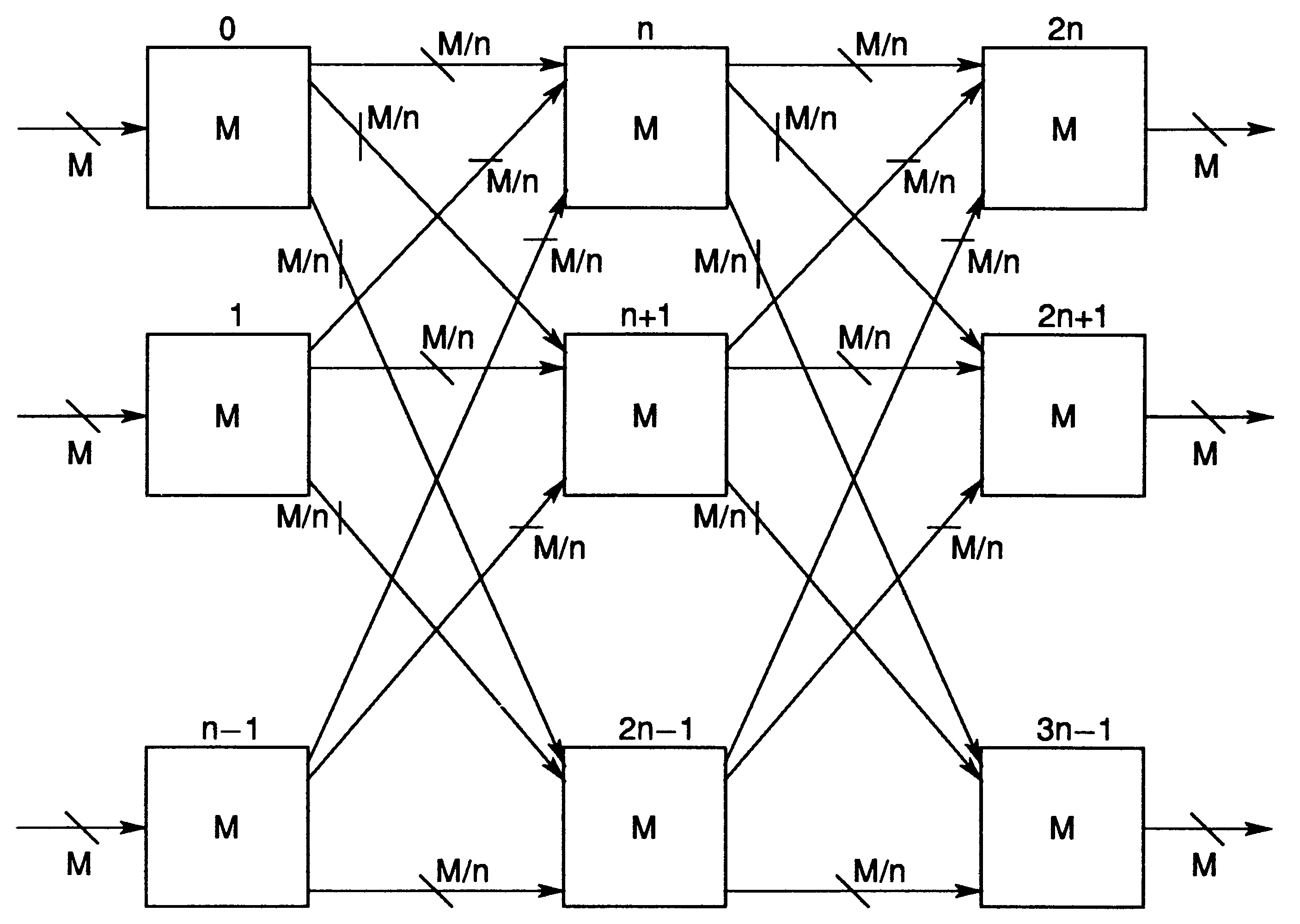
An arrangement which does satisfy this requirement is shown in figure 11. This uses 3n elements of size M to implement an nM-way crossbar where n ≤ M. A crossbar switch with M inputs and M outputs can be used to design a crossbar with up to M2 inputs and M2 outputs. Note that it also has the property that each input to output connection will always be routed through three of the smaller elements.
But note that since we cannot have a fraction of a link, this description uses integer arithmetic. In general, therefore, it is possible to design a crossbar of size n(M - M mod n).
Using this assertion here are some examples for a C004 (where M=32):
| n | C004s | size of crossbar |
| 2 | 6 | 64 |
| 3 | 9 | 90 |
| 4 | 12 | 128 |
| 5 | 15 | 150 |
| . | . | . |
| . | . | . |
| 32 | 96 | 1024 |
From section 3.1, it can be seen that three IMS C004’s can be cascaded to derive a 48-way crossbar, and from section 3.2 that 3n IMS C004’s can be used to achieve a crossbar of size n(32 - 32 mod n) for n ≤ 32.
Sometimes a choice must be made between the two design techniques. For example If two 45-way crossbars are required, then the first design could be implemented using six IMS C004’s (three IMS C004’s for each crossbar). Alternatively, two 45-way crossbars are a subset of a single 90-way crossbar (which has the bonus of extra flexibility), and this can be implemented using nine IMS C004’s in the second design. If such a choice is to be made then the following properties should be considered. The first design will route each link path through 1, 2 or 3 IMS C004s, whereas the other will always route through three IMS C004’s. The average link delay of the first will therefore be smaller, which will usually be preferable, but a fixed link delay might be more desirable. The software support for setting up the second cascade is simpler because the design is more uniform and the crossbar is more flexible. Finally the first design will use fewer IMS C004’s.
The design suggested in this section makes use of the property that all four transputer links are identical. This means that as far as the configuration software is concerned, it doesn’t care on which link a hard channel is placed, provided that each is connected o the transputer specified by that software. Because of this we can choose any link numbering scheme when trying to configure a network with crossbars.
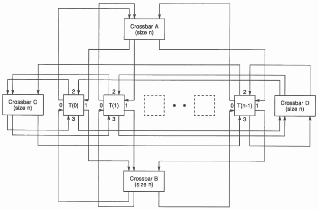
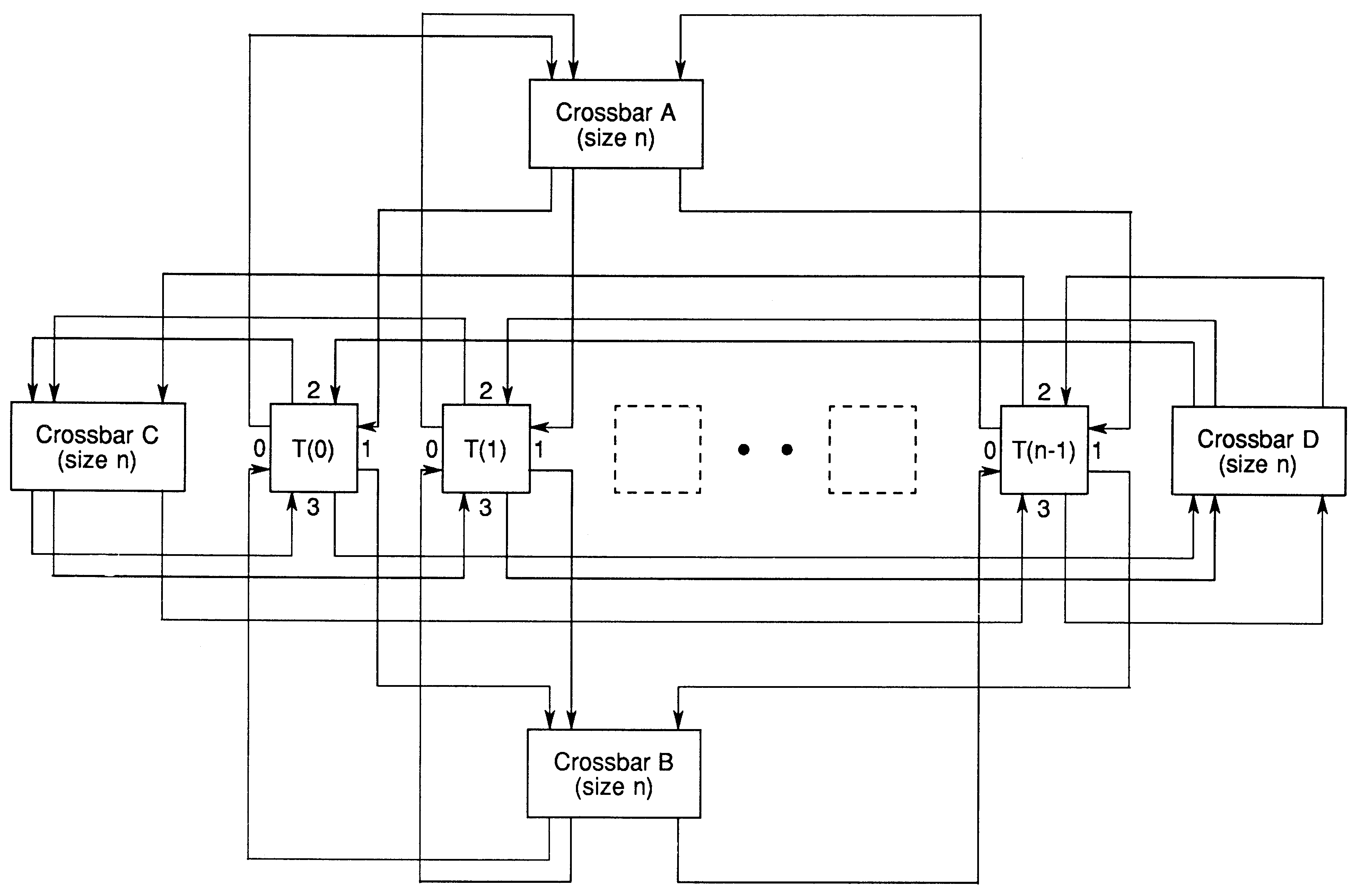
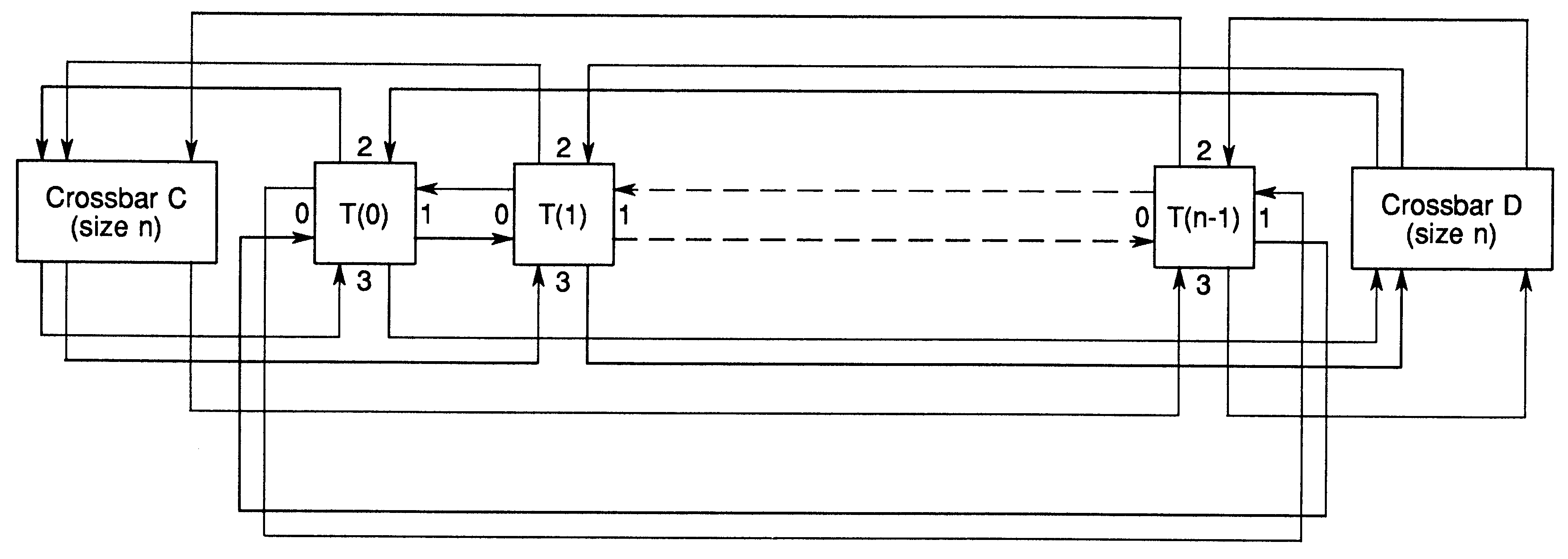
It is always possible to set a network of transputers to any configuration using just four crossbars. The size of the crossbars should be at least as great as the number of transputers in the network. For example, a 32 node network can be configured using four IMS C004’s, and a 48 node network can be configured using twelve (making use of an IMS C004 cascade arranged as shown in figure 8). Although a complete proof of this statement is outside the scope of this text, we will show how this can be achieved for configurations that contain a Hamitonian Cycle (i.e. a route through the network that visits every node once only). This method will be applicable to most interesting configurations. The hardware arrangement is as shown in figure 4. Note that crossbar A connects link 0 outputs to link 1 inputs, crossbar B connects link 1 outputs to link 0 inputs, and crossbars C and D similarly connect links 2 and 3.
Firstly, find a Hamiltonian Cycle (if one exists) through the network and choose a link 0 to link 1 connection between all transputers. Since any link 0 can be connected to any link 1 by crossbars A and B this cycle can be configured.
Now each transputer has just two links left to connect. Again since these links are identical, we do not care which links we choose when connecting our configuration.
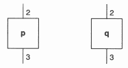
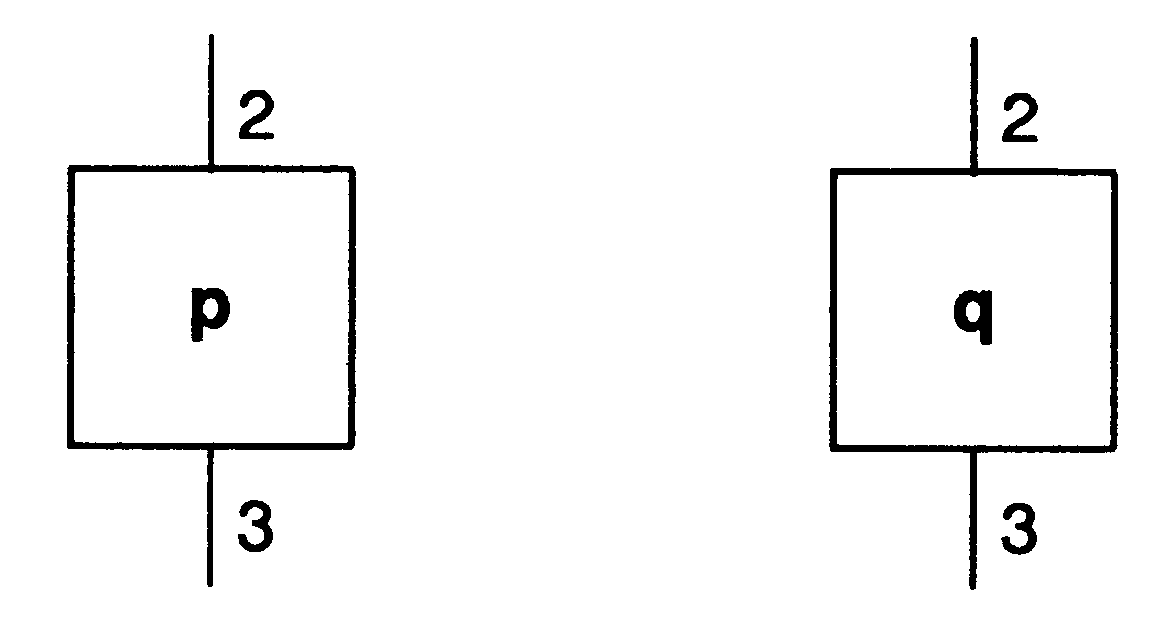
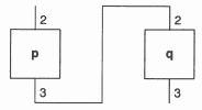
If, for example, transputer p is to be connected to transputer q (figure 13) and so far no other connections have been made, a link 2 to link 3 connection can be made in one of two ways. Having made this connection (figure 14), transputer q link 3 can be connected to link 2 of any other transputer in the network (including p). If another link between p and q is required, these transputers will be completely connected (i.e. there cannot be other connections to them) and so the next link to be connected will be between two transputers with both link 2 and link 3 unconnected.
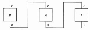
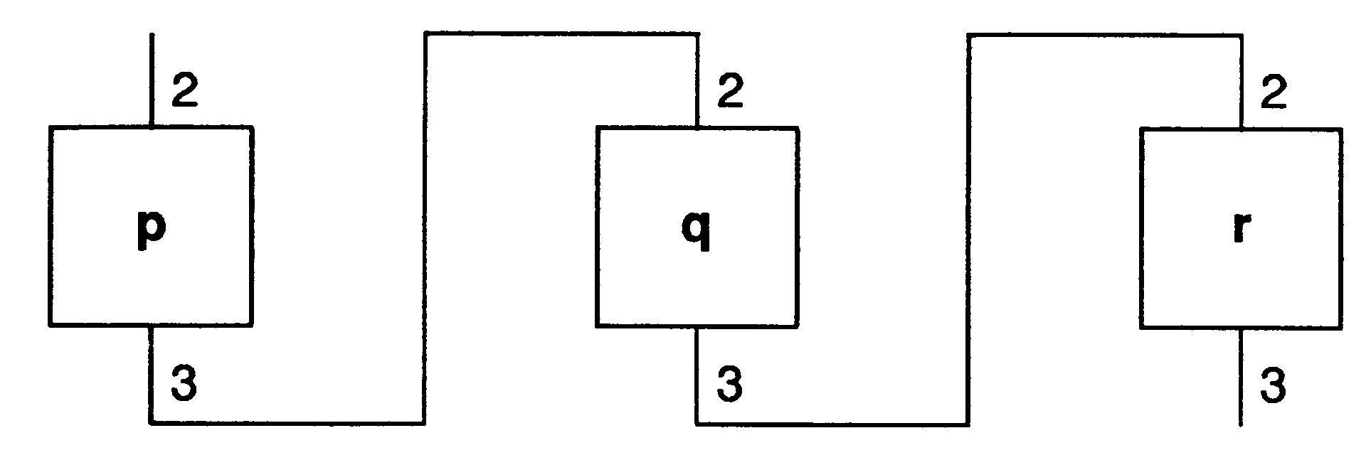
Assume now that q is connected to transputer r (figure 15). link 3 of transputer r can be connected to link 2 of any other transputer in the network with the exception of transputer q. But since link 2 and link 3 of q have already been connected, it will not be required to connect another link to it in a four link configuration. If a link between r and p is required, we again have a completely connected group.
Hence, by induction, it is always possible to arrange that all links 2 are connected to links 3 and vice-versa: This can be achieved using crossbars C and D in figure 4.
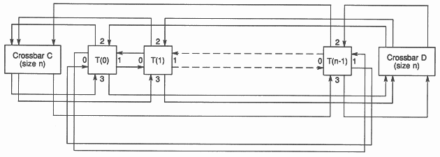
In the previous section, advantage was taken of the fact that all transputer links are identical. It will often also be true that all transputers in the network are identical. If this is the case then the Hamiltonian Cycle (if it exists) can be a fixed pipeline through the network. This means that the link 0 to link 1 connections can be hardwired and all possible configurations can be obtained by connecting link 2 to link 3 using two crossbars as described above. A network of N transputers could then be configured using just two N-way crossbars. This arrangement is shown in figure 16.
For example 32 transputers can be completely configured using just two IMS C004s.
The use of the IMS C004 is not restricted to computer configuration applications. The ability to change the switch selling dynamically enables it to be used as a general purpose message router. This may of course also find applications in computing with the emergence of the new generation of supercomputers, but a more widespread use may be found commercially as a communication exchange.
This section considers one way in which an exchange might be implemented. A suitable protocol for this example is shown using Hoare’s CSP notation [CAR Hoare: Communicating Sequential Processes] in section 8. A possible occam implementation is included below for users unfamiliar with CSP. There is no reason why this exchange should not be expanded with a larger crossbar, making use of the design techniques of section 3.
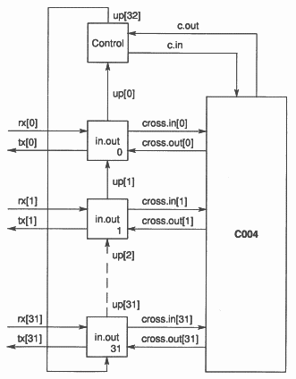
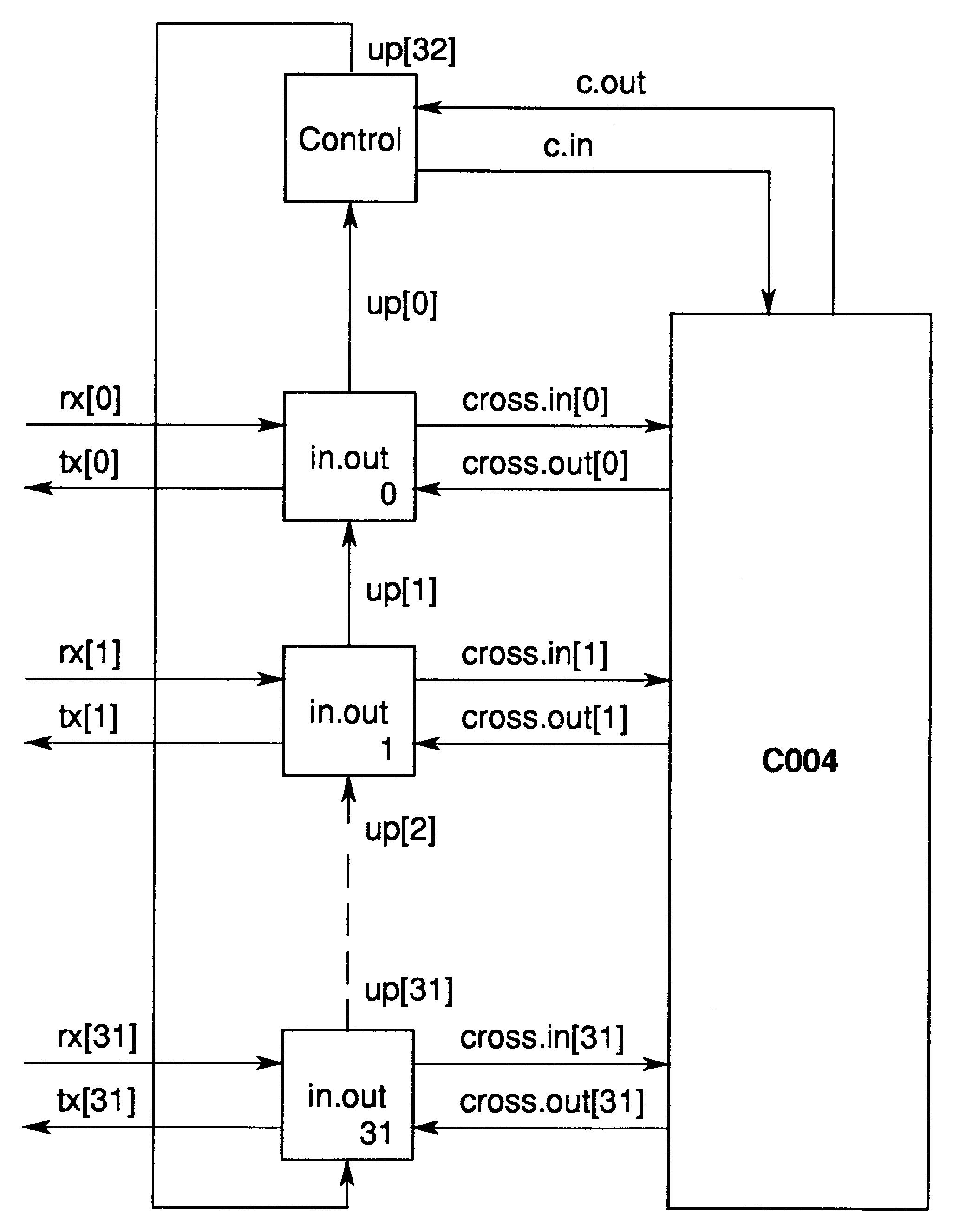
A message into the exchange must be preceded by a destination token. When this message is routed through the exchange, the destination token is replaced with a source token so that the receiver knows where the message has come from. The input.output processes of figure 17 and the controller processes could be implemented easily with INMOS IMS T212 transputers, and the link protocol for establishing communication with these devices can be interfaced with INMOS link adaptors. In this configuration two channels are placed on each IMS C004 link in opposite directions.
This section provides some occam code that could be used to implement the exchange described in section 8. Its main purpose within the context of this document is to give an alternative way of describing the example for the reader who is unfamiliar with CSP. For this reason, declarations have been omitted except where confusion might arise without (figure 17).
PLACED PAR PROCESSOR no.of.nodes T2 controller (c.in, c.out, up[0], up[no.of.nodes]) PLACED PAR i = 0 FOR no.of.nodes PROCESSOR i T2 input.output (BYTE i, rx[i], tx[i], up[i], up[i+1], cross.in[i], cross.out[i]) |
The code for this process should be loaded onto the transputer that talks to the IMS C004 via its configuration link. It receives a token from hard channel up.in and, depending on the value of that token, takes one of three paths before repeating.
PROC controller (CHAN c.in, c.out,
up.in, up.out) WHILE TRUE SEQ up.in ? token IF token = et.ack -- consume rest of acknowledge packet since -- it has done its job up.in ? any.byte; any.byte token = et.req ... deal with request -- (i) token = et.rel ... setup link or send new request -- (ii) : |
i. deal with request
This firstly receives the rest of the request packet. It then finds out which nodes are currently connected to the two that want to talk to each other and sends a release packet to inform the relevant nodes that a new link is about to be set up.
{{{ deal with request
SEQ up.in ? source; dest c.in ! ct.enquire; source c.out ? current.source.conn -- address of node currently -- connected to source set.to.nil.if.inactive (current.source.conn) -- (iii) c.in ! ct.enquire; dest c.out ? current.dest.conn -- address of node currently -- connected to dest set.to.nil.if.inactive (current.dest.conn) -- (iii) up.out! et.rel; current.source.conn; current.dest.conn; source; dest }}} |
ii. setup link or send new request
This firstly receives the rest of the release packet. It then proceeds to find out what is currently connected to the two that want to communicate. If the same as before (i.e. when this was done before sending the release packet) then the previous connections are disconnected, the new link is set up, and an acknowledge packet is transmitted. Otherwise a new release packet is sent.
{{{ setup link or send new request
SEQ up.in ? last.source.conn; last.dest.conn; source; dest c.in ! ct.enquire; source c.out ? current.source.conn set.to.nil.if.inactive (current.source.conn) -- (iii) c.in ! ct.enquire; dest c.out ? current.dest.conn set.to.nil.if.inactive (current.dest.conn) -- (iii) IF (last.source.conn = current.source.conn) AND (last.dest.conn = current.dest.conn) -- IMS C004 setup has not affected these node connections -- since the release packet was transmitted SEQ -- disconnect current.source.conn and source IF current.source.conn = byte.nil SKIP TRUE -- disable current connection to source c.in ! ct.disconnect.link; current.source.conn; source -- disconnect current.dest.conn and dest IF current.dest.conn = byte.nil SKIP TRUE -- disable current connection to dest c.in ! ct.disconnect.link; current.dest.conn; dest c.in ! ct.link; source; dest up.out! et.ack; source; dest TRUE SEQ -- transmit a new release packet up.out ! et.rel; current.source.conn; current.dest.conn; source; dest }}} |
iii. set.to.nil.if.inactive
If bit 7 of the parameter output.conn is 1, then the connection is inactive and the byte is set to address nil. Otherwise it is unchanged. This could not be expressed in detail in the CSP description.
PROC set.to.nil.if.inactive (BYTE output.conn)
IF (output.conn BITAND (BYTE #80)) = (BYTE #80) output.conn := byte.nil TRUE SKIP : |
The code for this process should be loaded onto all the other transputers. The state is initially inactive. If a message is received from the IMS C004 on switch.in then it is passed on via data.out. If a command packet is received on up.in then it is dealt with as described in (iv). If a message is received on data.in then it is dealt with as described in (v). This repeats indefinitely. Note that a priority is given to the three input sequences. This could not be expressed in GSP.
PROC input.output (VAL BYTE i,
CHAN data.in, data.out, up.out, up.in, switch.out, switch.in) SEQ state := inactive d := byte.nil [max.mess]BYTE rx.mess: [max.mess]BYTE tx.mess: WHILE TRUE PRI ALT switch.in ? source; tx.length; [tx.mess FROM 0 FOR tx.length] data.out ! source; tx.length; [tx.mess FROM 0 FOR tx.length] up.in ? token ... deal with command packet -- (iv) ((state = active) OR (state = inactive)) & data.in ? dest; rx.mess; [rx.mess FROM 0 FOR rx.length] ... deal with message transfer : -- (v) |
iv. deal with command packet
If a release token has been received, the rest of the release packet is received and passed on to the next node. Now if the state is active and either dest, addr1 or addr2 are the same as the local identifier (i), then the state is set to inactive. Note that this is not necessary if the link that has been requested already exists, which may occur if the other end of the link has made the request prior to the existing setup.
If a request token has been received, the rest of the packet is received and passed on since this will only be analysed by the controller.
If an acknowledge token has been received, the rest of the packet is received and passed on. If the destination address is local (dest = i) then a new link path has been set up for this node and it becomes active. If the source address is local (source = i) then the request that was previously sent has now been acknowledged and the stored message can be sent to its destination via the IMS C004.
{{{ deal with command packet IF token = et.rel SEQ up.in ? addr1; addr2; source; dest -- pass release packet on to next node in daisy chain up.out ! et.rel; addr1; addr2; source; dest IF (state = active) AND ((((addr1 = i ) OR (addr2 = i)) OR (dest = i)) AND (NOT ((source=d) AND (dest=i)))) -- another node has requested a link to this node or its -- connected node is to be connected to another node state := inactive TRUE SKIP (token = et.req) OR (token = et.ack) SEQ up.in ? source; dest -- pass request or acknowledge packet on to -- next node in daisy chain up.out ! token; source; dest IF token = et.req SKIP token = et.ack IF (state = inactive) AND (dest = i) -- link has been set up with -- another node SEQ state := active d := source (state = pending) AND (source = i) -- the link that was previously requested -- has now been set up SEQ switch.out ! i; rx.length; [rx.mess FROM 0 FOR rx.length] state := active d := dest TRUE SKIP }}} |
v. deal with message transfer
A message has been received with an associated destination. If the state of the process is active and the destination is that already set up (dest = d) then the message can be immediately routed through the IMS C004. Otherwise a request is sent to the controller to set up a new link path and the state is set to pending.
{{{ deal with message transfer
SEQ IF (state = active) AND (dest = d) -- the destination requested by the message -- received is the one that is currently -- connected by the IMS C004 switch.out ! i; rx.length; [rx.mess FROM 0 FOR rx.length] (state = active) OR (state = inactive) -- a new link needs to be requested SEQ up.out ! et.req; i; dest state := pending }}} |
In general the transputer handles long messages more efficiently than short messages. However, with the code given here, while a message transfer is occurring, two input.output processes of the bidirectional exchange will become busy and will not be able to pass information to the controller. For this reason messages should be kept short and long messages should be broken into short ones. In the case, for example, when all routes are active in transferring data between fixed destinations and sources, there need not be any communication to the controller until a particular source decides it wants to talk to another destination. Therefore for the exchange to operate efficiently each input.output process would be expected to be predominantly in the active state.
A single IMS C004 can be used alone as a 32x32 crossbar supporting INMOS link protocol. Alternatively, since it is a digital device, a number of IMS C004’s can be used to construct a larger crossbar without any other hardware. Since it introduces a small real time communication delay, the data transmission rate will be reduced when cascading more than one IMS C004.
With careful design and suitable software support, a small number of IMS C004’s can be used to completely connect any configuration of a large network of transputers without any loss of generality.
Since it can be dynamically programmed, its applications can be extended to systems that might not use transputers. The INMOS link adaptor enables any parallel bus users to take advantage of the flexibility of the device. The design of a message routing exchange is fairly straightforward.
The sections ”CSP description of IMS C004” and ”CSP description of a 32 stage bidirectional exchange” has been omitted.