|
|
| Configuring Occam Programs _____________________________________________________________________ |
| Laurie Pegrum January 1988 |
Copyright notice
This document refers to the software release available from Inmos as of June 1987. The
examples take advantage of features, specifically libraries and variant protocols, which
may not be supported in earlier implementations of the TDS.
The occam text in this technical note was written by Laurie Pegrum of Inmos Ltd 1987.
It is offered free of charge with no technical support.
Copyright Inmos Ltd 1987.
The recipient is authorised by Inmos to copy the occam text and modify it. Copyright in
any modifications shall belong to the recipient.
Except for liability arising from due course of law, Inmos accepts no liabilities
whatsoever with respect to this document or its use.
Since the launch of the transputer [1] in 1985 there has been and continues to be a growth in the use of multi-processor systems. The benefits of removing the hardware bottlenecks of a single processing element are becoming more obvious to those now reaching the speed limitations of their current systems.
The INMOS transputer has made multiprocessor design trivially simple. Minimal additional circuitry and radical space saving using the INMOS serial links have made it possible to put many computing elements onto a single board. A goad example of this is the INMOS Evaluation Board IMSB003, described in technical note 10 [2], which is only sparsely populated with four transputers.
The transputer is designed to be extremely efficient at running the high level language occam [3]. occam supports constructs for precise handling of communications and synchronisation, essential in multi-processor environments.
To develop software for transputer based applications INMOS supplies the Transputer Development System. The system discussed here is the IMSD701 system for the IBM XT/AT as described in the promotional literature INMOS Spectrum [4]. This system offers an occam compiler for creating occam code for individual transputers. In addition there is a configurer for the placement and loading of code into a multi-transputer network.
Thus today there are two issues relating to the programming of transputer networks. First the programmer must express his problem as a number of parallel processes. To achieve his performance requirements he can then configure his application to run on more than one transputer. It is the issues relating to this configuration that are looked at here.
In an ideal world it would be exactly the same code running on one transputer that one would run on a network. In reality today however, the user must add information relating to the topology of the link connections and on which transputer a piece of code is to be run. If the user has given no thought to his system design in advance then he may need to add additional occam processes for routing his application on a network. This can be avoided by a modicum of foresight. An application that runs on x transputers should include more than x parallel processes. In the design of these the programmer should be aware of the number of links available on the transputers in the network. One transputer link implements two occam channels, one in each direction.
After configuration the programmer may wish to make changes to his code to enhance performance. This issue is treated separately in the technical note on performance maximisation [5]. As the programmer develops code for his network it will change from that used for programming a single transputer. Changes will relate to performance, issues of priorities and link usage which are added to the original application code. Despite these changes being made when moving from one transputer to many, the mapping of multi-transputer code onto a single processor is often trivial. The exception to this is when the code takes advantage of features local to specific processors. In particular one transputer may not support enough memory to run all the network’s code. Programs for specific transputer networks will evolve as the programmer takes advantage of features of his network; for example, building a transputer based machine and wanting to append another device via a link adaptor. A change might then be required to include the new hardware data stream into the software.
The configurer is a tool in the system designer’s armoury for having ultimate control of all his software and how it relates to his hardware. It is not used in isolation but as part of the design phase for a transputer system. Thus the following example must include occam program development to show practical usage of the configurer.
This technical note goes through 4 stages of program development.
The application used is sorting a stream of data into numerical order. The basic algorithm is discussed in the occam tutorial [3]. This algorithm yields a number of similar parallel processes which can be mapped straightforwardly onto a transputer network. The code for one of these processes is listed below.
PROC element (CHAN OF letters input, output)
INT highest, next: BOOL going, inline: SEQ going := TRUE WHILE going input ? CASE terminate going = FALSE letter; highest SEQ inline := TRUE WHILE inline input ? CASE letter; next IF next > highest SEQ output ! letter; highest highest := next TRUE output ! letter; next end.of.letters SEQ inline := FALSE output ! letter; highest output ! end.of.letters output ! terminate : |
This coded algorithm is wrapped in a fold labelled:
... element
|
The occam tutorial example has been adapted to have a WHILE loop instead of a replicated sequence in order to sort variable length strings of characters. An outer WHILE separates global program termination from terminating the end of character sequences. Other differences involve using a variant protocol for communicating letters between sorting elements
PROTOCOL letters
CASE letter; INT end.of.letters terminate : |
An EXE foldset identifies a user defined occam program. The occam program takes the form of a procedure declaration with a number of fixed formal parameters. These parameters are occam I/O channels which give an EXE the use of the host keyboard, screen and filing system.
Within the occam program there may be other procedure declarations. Should these contain all the information for their compilation then they may be separately compiled in SC folds. These folds are needed for both the creation of library routines and configuration.
The benefit of using the library mechanism is that procedures can be compiled in one location and then referred to by many programs. The mechanism also incorporates the inclusion of constants and protocols within library folds. The following examples use three user defined libraries.
Thus the outer level view in the TDS would look like this:
{{{ stage 1 running the application and interface as an EXE
...F header.tsr ...F problem.tsr ...F monitor.tsr ... EXE harness.tsr }}} |
The three opening and dosing curly braces denote a fold that is currently open so that we can look inside. The three dots mark a fold that is closed so we cannot see its contents. The F following a fold marker shows the fold to be a file under the host operating system. All the text strings in the above listing are comments as they are on the same lines as the fold markers. These have no effect on the contents of the folds whatsoever. All the occam source text is contained within the folds and thus hidden from our current viewpoint.
The three folds marked with an F contain libraries. The last fold is an EXE fold. This special fold attribute is put there at the users request by using a special compiler utility called make.foldset. This is not the same as just writing EXE in a comment as the fold attribute will not be set. The fold attribute is required by the compiler to distinguish compilable folds from any others.
We now look briefly into these folds to illustrate the structure therein.
Library folds are created by using the make. foldset utility on an empty fold. The library contents can then be placed inside the LIB fold beneath the fold marked Library ID which contains the library version number. Valid library contents include compiled SC fold bundles and text folds containing PROTOCOL or constant declarations. All LIB folds require validating before they can be referenced. This is to guarantee that the version number changes when the library is changed.
To reference a library the validated LIB fold must be put into a file. It is not possible to file compilation foldsets such as SC, EXE or LIB. To file a library a text fold must be made around the LIB fold and the text fold must then be filed. It is the name of this file in the host operating system that is used to reference the library.
The header.tsr file fold contains constants and protocols used in the rest of this technical note. The most important parts of this library are the protocol definitions for string and letter.
{{{F header.tsr
{{{ LIB ... Library ID {{{ protocols PROTOCOL string IS INT::[]BYTE: PROTOCOL letters CASE letter; INT end.of.letters terminate : }}} ... program constants ... link numbers }}} }}} |
As will be seen shortly, the string protocol is used for communicating between the monitor interface and the application program. These programs are running in parallel with each other and will henceforth be referred to as parallel processes.
The application is made up of many parallel element processes, all of which communicate using the letters protocol. The letters protocol is a variant protocol. This is the method by which differing types of data may be communicated using the same occam channel. With a variant protocol every communication is preceded by a tag to identify the type of the data to follow. These tag names are defined by the programmer. When the tag name itself conveys the desired message then no further communication is required. The application reads a stream of letters followed by an end.of.letters tag. This is followed by either another stream of letters or a terminate tag.
The program constants are selected values from the grand assortment available for interfacing with the TDS. The link numbers are the occam addresses of the INMOS serial links as defined in the relevant transputer datasheet.
The application chosen for this technical note is made up from a number of element processes as described earlier. In addition to this are two other procedures called inputter and outputter. These have been collectively put into a SC (separate compilation) fold and then placed inside a library fold.
{{{F problem.tsr
{{{ LIB ... Library ID {{{ SC application PROCs, inputter, element and outputter {{{F application PROCs, inputter, element and outputter #USE "header.tsr" ... PROC inputter (CHAN OF string input, CHAN OF letters output) ... PROC element (CHAN OF letters input, output) ... PROC outputter(CHAN OF letters input, CHAN OF string output) }}} }}} }}} }}} |
The operation of inputter is to input a string and then to supply this as a sequence of letters to a pipeline of element processes. The outputter procedure reads the resultant stream of letters and packs them back into a string for communication onwards. The communication protocol of string is used as standard amongst my application programs. The string communication is far more efficient for link communication as the link can communicate all the data before attempting to gain more processing time. The concept of communicating data in large arrays rather than byte-by-byte can have a dramatic effect on performance [5].
The design of these three procedures is such that they should all be instanced as parallel processes, communicating with one another using occam channels.
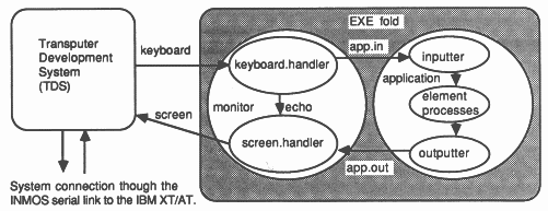
The final library involved in this example is one that contains the interface with the TDS. This is a procedure called monitor that supplies the values of keystrokes on the host keyboard to the application whilst in parallel conveying data and result outputs to the host screen.
{{{F monitor.tsr
{{{ LIB ... Library ID {{{ SC monitor.tsr {{{F monsource.tsr #USE "header.tsr" PROC monitor (CHAN OF ANY keyboard, screen, CHAN OF string app.in, app.out, VAL BOOL using.subsystem) ... PROC keyboard.handler ... PROC screen.handler CHAN OF INT echo: PAR keyboard.handler (keyboard, echo, app.in) screen.handler (app.out, echo, screen) : }}} }}} }}} }}} |
It is worthwhile expending effort in creating a version of monitor that is general purpose in scope. This procedure, running as a parallel process, converts the keyboard and screen I10 from the TDS into simple strings of bytes for the application. By using this monitor one can edit text strings in advance of sending them to the application. This means that the application program itself need not concern itself with erroneous strings, multiple carriage returns or case sensitivity. All these functions can be filtered out by the keyboard handler. The keystrokes made at the keyboard are sent down channel echo. The screen.handler can distinguish between keys typed by the user and strings supplied by the application. Thus the text can be put into different windows for clarity.
The use of the screen handler process enables it to be the only parallel process that needs to communicate using the TDS protocol. This not only makes the writing of other processes simpler but also makes them more portable. Should it be necessary to mount the application in a different system environment then it would only be the monitor that would need to be changed. This concept of modularity can be extended to allow monitor to be used with any configuration of transputers and quite probably used with different applications. The concept of modular blocks of reusable code is simple to realise in occam where parallel processes run independently from one another.
PROC keyboard.handler (CHAN OF ANY in,
CHAN OF INT out, CHAN OF string data) ... variables SEQ going := TRUE length := 0 WHILE going SEQ in ? char IF char = stopch ... terminate monitor and application if appropriate char = return ... pass string to application if non zero in length char = ft.del.chl ... user has typed the backspace key TRUE ... buffer char, all letters map to lower case : |
This is a good opportunity to note how folds should be used to show the structure of the occam text. As can be seen the keyboard handler procedure is an IF construct repeated many times within a WHILE.
Termination of parallel programs is the duty of the programmer. The termination of the monitor process is achieved by the user entering the stopch at the keyboard. The keyboard handler must then pass this character to the screen handler so that it will also terminate. This is done because an occam program can only terminate when all of its constituent parallel processes have terminated and in the monitor process the keyboard and screen handlers are running in parallel. One complication here is whether or not this termination request should be passed on to the application process as well. Referring back to the monitor process there is a parameter included called using.subsystem. This is set to either TRUE or FALSE depending on whether a subsystem of transputers has been connected to the host transputer. The decision taken was that if this was FALSE then no subsystem is connected and thus the application is also running on the host. In this case the termination request is passed on to the application so that it will also terminate when the monitor does. When running as an EXE this is essential to be able to return cleanly to the editor after execution. If using.subsystem is TRUE then it becomes inadvisable to pass on the termination request. There are two reasons for this. There is a benefit in being able to terminate the monitor but leave the application running. The programmer can set a job running and then return to the host to continue with other work rather than waste his time waiting. He can then return at his convenience to discover the progress made. There is also a danger in sending a final termination request should the target system have erred. This communication may never complete resulting in deadlock and thus rebooting the host to reach the editor again. This delays the analysis of the network which could then be undertaken by the host transputer. The detection of a subsystem error is left to the screen handler.
PROC screen.handler (CHAN OF string data,
CHAN OF INT in, CHAN OF ANY out) ... constants, procedures and variables SEQ ... initialise {{{ body WHILE going.in OR ((NOT using.subsystem) AND going.data) SEQ clock ? waketime waketime := waketime PLUS one.hundreth.of.a.second ALT going.in & in ? char ... print keyboard character on screen going.data & data ? length::string ... print data from application on screen monitoring & clock ? AFTER waketime ... if monitoring is TRUE, poll subsystem error pin draw.cursor (window[1]) }}} : |
The screen handler is repeatedly searching for one of three alternatives. Either keyboard characters are echoed, a string of data comes from the application or a timeout happens should neither of the other two have occurred in one hundredth of a second. Should the timeout occur then the program tests the subsystem error bit which is connected to all the target transputer error pins ored together. If this detects an error then a message to the user is issued whereafter the user can then terminate the monitor and reenter the TDS for subsequent analysis.
The ALT construct runs separate code for when data is input from the keyboard or from the application. This makes it simple to implement a windowing system to distinguish the two output streams in the eyes of the user.
Every guard in the ALT statement is headed by a boolean flag. This is used to allow channels to be disabled under certain conditions. For example when the termination character is echoed from the keyboard handler then going.in is set to FALSE as we should expect no further keyboard inputs. Likewise when subsystem error is detected monitoring is set FALSE as there is no point in polling now that the error is known.
If the TDS is executing on an IMSB004 transputer evaluation board then the subsystem logic is decoded through a PAL that can be accessed by software [6]. The subsystem reset and error are at machine address zero in the middle of the transputer’s address space. Occam addresses start from zero and are word aligned so we can access the subsystem by placing a variable at #20000000. Reading this variable and finding bit zero set detects the assertion of the subsystem error pin. Subsystem analyse can be asserted by writing 1 to a variable placed at #20000001.
It is only worth reading the subsystem error when there is a network of transputers connected to the subsystem port. Thus the value of monitoring should be initialised to using.subsystem. Thus when we run the entire application as an EXE on the IMSB004 the subsystem error pin is not polled.
We now bring our three libraries together and instance them inside an EXE fold. For an EXE fold the parameters keyboard and screen are now bound to channels which communicate to the respective host hardware.
{{{ EXE harness.tsr
{{{F harness.tsr PROC harness (CHAN OF ANY keyboard, screen) #USE "header.tsr" -- program constants #USE "monitor.tsr" -- EXE interface to TDS #USE "problem.tsr" -- PROCs used in application CHAN OF string app.in, app.out: PAR monitor (keyboard, screen, app.in, app.out, FALSE) {{{ application [string.length+1]CHAN OF letters pipe: PAR inputter (app.in, pipe[0]) PAR i = 0 FOR string.length element (pipe[i], pipe[i+1]) outputter (pipe[string.length], app.out) }}} : }}} }}} |
The program is to run the monitor in parallel with the application. The application itself is made up of inputter, outputter and a replicated instance of the element procedure. Thus in total we have string.length + 3 processes running in parallel. It is recommended that whenever a PAR construct is used a diagram should be included to explain the connectivity and direction of data transfer. In this we model parallel processes with circles and the data channels between them as arrows.
|
|
The code in this form can be tested and debugged on the host transputer alone. We now begin to distribute some of these parallel processes onto other transputers.
We now look at how the application program can be run on a second transputer. This leaves the first transputer free to run the development system and also to monitor the behaviour of the other transputer, i.e. the target system.
To achieve this result the occam code for the application must be split apart from that code used for monitoring. This has already been planned for by defining the code modules in separate procedure declarations. It is now a relatively easy matter of putting the application PROGRAM onto the target system whilst running the monitor EXE on the host transputer.
Consideration must also be given to how the host and target transputers are to be connected. All hardware connections made, by connecting INMOS serial links together, must be matched by a corresponding description of the connection in the software. Without this connectivity specification the system would have no knowledge of which links were usable or of where they were connected.
The placement of occam code modules onto distinct processors along with a connectivity specification forms the body of a PROGRAM fold. The PROGRAM fold defines the behaviour of the target system of transputers; in our current example a single transputer.
Like other fold types, a PROGRAM fold is created by using the make.foldset utility in either the compiler or configurer toolsets. It is when PROGRAMS start to be used that the configurer toolset is needed more frequently. There are occasions when both the compiler and configurer toolsets may be needed shortly after one another. For this reason there is a combined toolset that integrates the functions of compilation and configuration when applied to PROGRAM folds.
For a single target transputer the PROGRAM fold should contain one separately compiled procedure, or SC fold, and the configuration information about the target hardware.
{{{ PROGRAM prog1
{{{F prog1.tsr ... SC app.tsr ... configuration }}} }}} |
The SC contains the application code used earlier. Note that the application code had to be in parallel with other processes in order to be able to move the code to another processor. The fact that distributed parallel processes are on separate processors with separate memory spaces is one reason why occam prohibits the use of shared variables.
{{{ PROGRAM prog1
{{{F prog1.tsr {{{ SC app.tsr {{(F app.tsr #USE "header.tsr" #USE "problem.tsr" PROC application (CHAN OF string in, out) [string.length+1]CHAN OF letters pipe: PAR inputter (in, pipe[0]) PAR i = 0 FOR string.length element (pipe[i], pipe[i+1]) outputter (pipe[string.length], out) ; }}} }}} ... configuration }}} }}} |
The application code is unchanged although we have now added a procedure declaration around it. The procedure is needed to provide a name, entry point and parameters for calling this module of code. Once wrapped in an SC fold, again by using the make.foldset utility, this occam code can be compiled to produce corresponding transputer code.
Notice that all the information needed for the application code must be contained inside the SC fold, including the library references. Apart from readability, the library calls are at the start of the SC fold for the compiler to understand the definition of string used in the SC procedure’s parameter list.
{{{ PROGRAM prog1
{{{F prog1.tsr ... SC app.tsr {{{ configuration ... link constants CHAN OF ANY app.in, app.out: PROCESSOR 0 T4 PLACE app.in AT link0in: PLACE app.out AT link0out: application (app.in, app.out) }}} }}} }}} |
The configuration is a simple placement of the SC procedure application onto a transputer which we have given the logical number zero. We must also state what type of transputer this is, in our case a T4, denoting a 32 bit integer transputer. The other types might have been T2 for a 16 bit transputer or T8 for a 32 bit floating point transputer. The type of the transputer is needed for the system to know how to initialise it at boot time. There will also be a check to make sure that application was compiled with the compiler parameter target.processor set to T4.
The instance of application has two actual channel parameters, app.in and app.out. These instance the formal channel parameters in and out in the procedure parameter list. Note that app.in and app.out must be specified in the configuration detail where we meet a limitation of the current configurer. The configurer only understands CHAN OF ANY and no other type of protocol. To compensate for this the configurer will not match the protocol types between different SCs in a PROGRAM. If it did this PROGRAM would be invalid due to the mismatch between formal and actual parameter types. It can be expected that this matching will be introduced and that the configurer will accept other protocols in a future implementation.
The above deals with the placement of the code module called application onto a transputer. The configuration must also include the topology of the link connections in the system and how this relates to the communication channels used in the software. This is achieved using the PLACE statement to map an occam channel onto the address of the transputer’s serial link hardware. These addresses, or link constants, can be found in the transputer datasheet. For the above example the communication on app.in and app.out has been directed onto transputer link zero, the link’s bidirectional communication supporting two occam channels.
If we loaded this PROGRAM into the target transputer it would run until the first communication made on app.in or app.out. It is up to the programmer to connect a system to this link to communicate with the application in order for it to continue, without which it would wait forever. All occam channels support synchronisation between inputting and outputting processes on a channel, they must both be ready to communicate for f to proceed. For this example we must connect the monitor to link zero in order to supply the data to start application running. The monitor process communicates with the TDS and therefore runs on the host transputer as an EXE within the TDS.
{{{ EXE interface
{{{F interface PROC harness (CHAN OF ANY keyboard, screen) #USE "header.tsr" #USE "monitor.tsr" CHAN OF string app.in, app.out: PLACE app.in AT linkout2: PLACE app.out AT linkin2: monitor (keyboard, screen, app.in, app.out, TRUE) : }}} }}} }}} }}} |
The EXE required is an instance of the library procedure monitor with its channel parameters connected to the TDS keyboard/screen and the others to the application. To communicate with the target transputer the communications on app.in and app.out must be redirected to a link of the host transputer in order for the two transputers to communicate. The above example redirects communication to the host transputer link two which would have to be connected to link zero on the target transputer for this example to succeed.
The monitor procedure has its parameter using.subsystem set to TRUE. This enables monitor to give the programmer an error message should for any reason the target transputer set its error flag.
This is the recommended way of developing transputer code where on a target system error the host EXE can correctly terminate to enable the target system to be quickly and simply analysed. New target hardware can be developed with small amounts of memory, not needing to house the complete TDS. The application now has complete use of the internal RAM available in the target transputer.
The following steps are now required, in the following order, to run the application as described on a two transputer network
The example given shows the use of two transputers in a system. However only a single target transputer is involved with doing the work involved in the application, the host transputer being concerned with I/O and error detection. It is useful to preserve this idea of the TDS host being independent of the target system. When a transputer system designer comes to sell a transputer based product he should not include the TDS as part of that product (unless he enters into special listening agreement with Inmos).
We now go on to distribute the application itself over multiple transputers.
In this section we take the code, which is currently in a single SC, for the application and distribute it over four separate transputers. The assumption made here is that the four transputer target network is an IMSB003 transputer evaluation board [2]. The IMSB003 simplifies this system in that the control lines for reset, analyse and error are preconnected so that the host board can automatically reset all the transputers simultaneously when it is connected to the subsystem. In addition every transputer on the IMSB003 has two links available on the edge connector (links 0 and 1) whilst the other two are preconnected in a square array (links 2 and 3). The configuration used here takes advantage of these preconnections whereas if the reader has a different network he must make these physical connections in addition to those mentioned in this text.
{{{ PROGRAM prog4
{{{F prog4.tsr ... SC PROC interface ... SC PROC worker ... link constants -- number of transputers must match value used inside SCs VAL number.of.transputers IS 4: ... configuration }}} }}} |
|
|
This example has two separately compiled procedures. interface connects to the monitor as well as doing string to letter protocol conversions and some element processes. worker is a number of element processes running in a pipeline. The number of element processes on each transputer depends on the number of transputers available hence the constant number, of.transputers. This constant is needed at configuration level, as will be seen later, and in every SC fold which must also contain a copy of number.of.transputers in order to be separately compiled.
#USE "header.tsr"
#USE "problem.tsr" {{{ extra constants for configuring for 4 transputers VAL number.of.transputers IS 4: VAL number.of.elements IS string.length: VAL elements.per.transputet IS number.of.elements/number.of.transputers: VAL remaining.elements IS number.of.elements - (elements.per.transputer * number.of.transputers): }}} PROC interface (CHAN OF string from.host, to.host, CHAN OF letters to.pipe, from.pipe) VAL elements IS elements.per.transputer + remaining.elements: [elements]CHAN OF letters pipe: PRI PAR PAR -- prioritise processes using links inputter (from.host, pipe[0]) element (pipe[elements - 1], to.pipe) outputter (from.pipe, to.host) PAR i = 0 FOR elements - 1 element (pipe[i], pipe[i+1]) : |
The application used here has a considerable amount of parallelism. It is the specification of problem in such a manner that enables us to now take advantage of parallel processing.
The separately compiled procedure interface has three processes at high priority and a number at low priority. The high priority processes are those which communicate with the Inmos serial links whereas the others only use internal channels. This prioritisation of link communication can enhance the throughput of pipelined systems [5]. All the above processes, regardless of priority, are running in parallel with each other.
The number of element processes in interface depends on number.of.transputers and how many element processes all the other transputers have. The total number of element processes in the target system must add up to number.of.elements in order to be the same application specification used previously. If the value of string.length is dividable by four then interface will include one quarter of the required element processes.
#USE "header.tsr"
#USE "problem. tsr" ... extra constants for configuring for 4 transputers PROC worker (CHAN OF letters in, out) VAL elements IS elements.per.transputer: [elements]CHAN OF letters pipe: PRI PAR PAR -- prioritise getting the links started element (in, pipe[0]) element (pipe[elements-2], out) PAR i = 0 FOR elements - 2 element (pipe[i], pipe[i+1]) : |
The separately compiled procedure worker comprises one quarter of the required element processes in a pipeline. We again take the opportunity of running the two processes that have channels mapped onto links at high priority with the remainder at low priority for performance reasons.
To keep compatibility with the previous example the link communication between workers and interface is now of protocol letter. An optimised system might use more inputter and outputter processes to convert to protocol string thus increasing the amount of data transferred with every link synchronisation. Such changes should be done after this example has been debugged as validating this will validate the algorithm and configuration specification of the system.
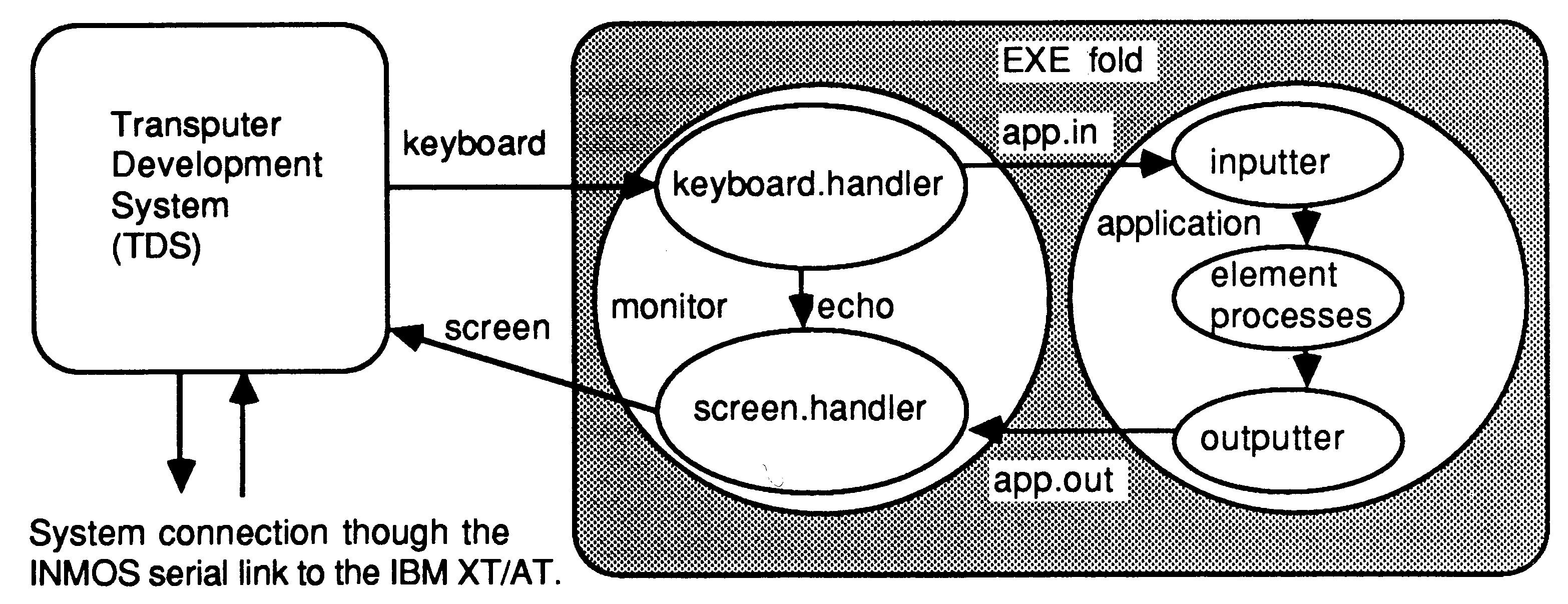
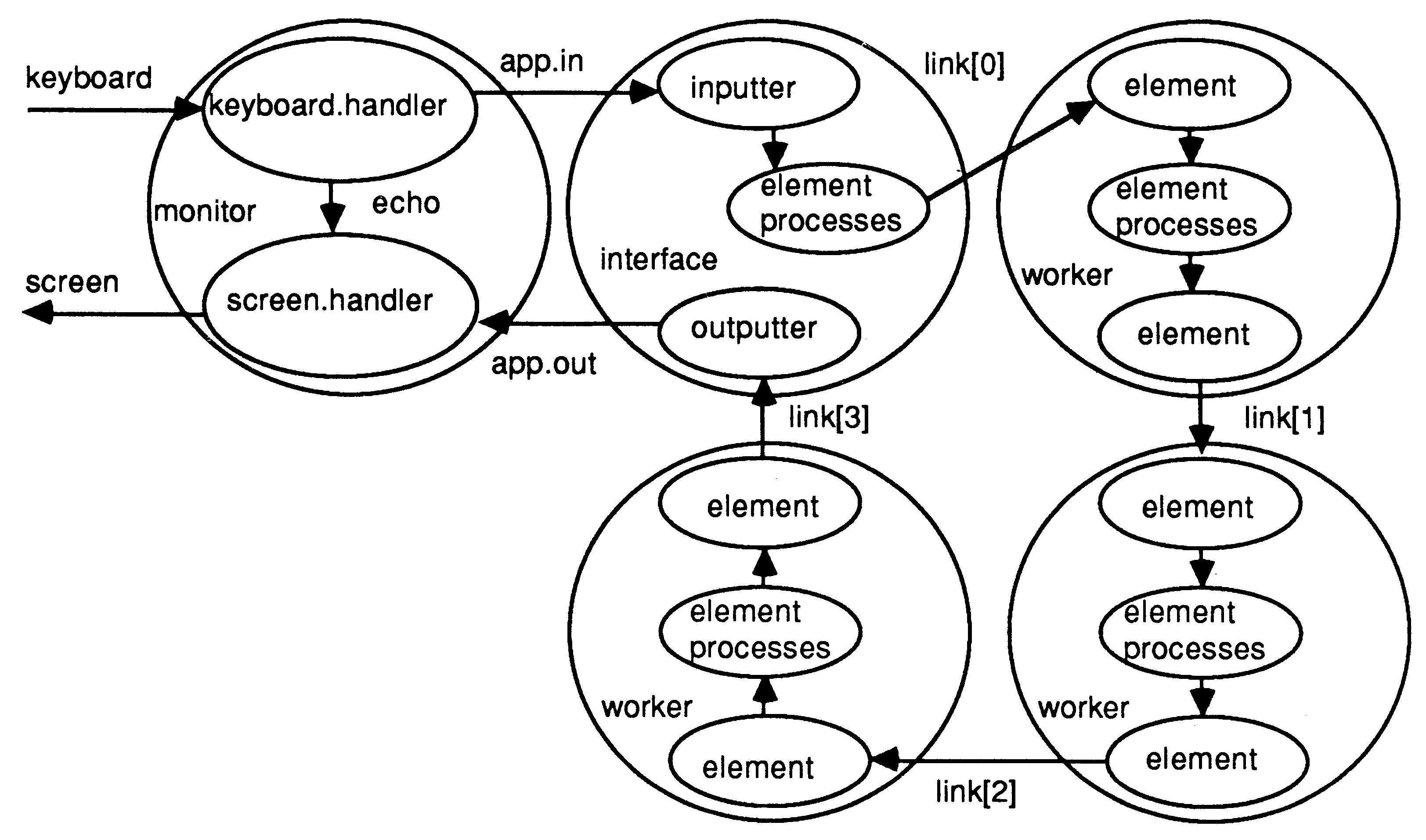
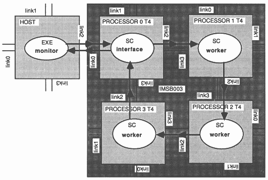
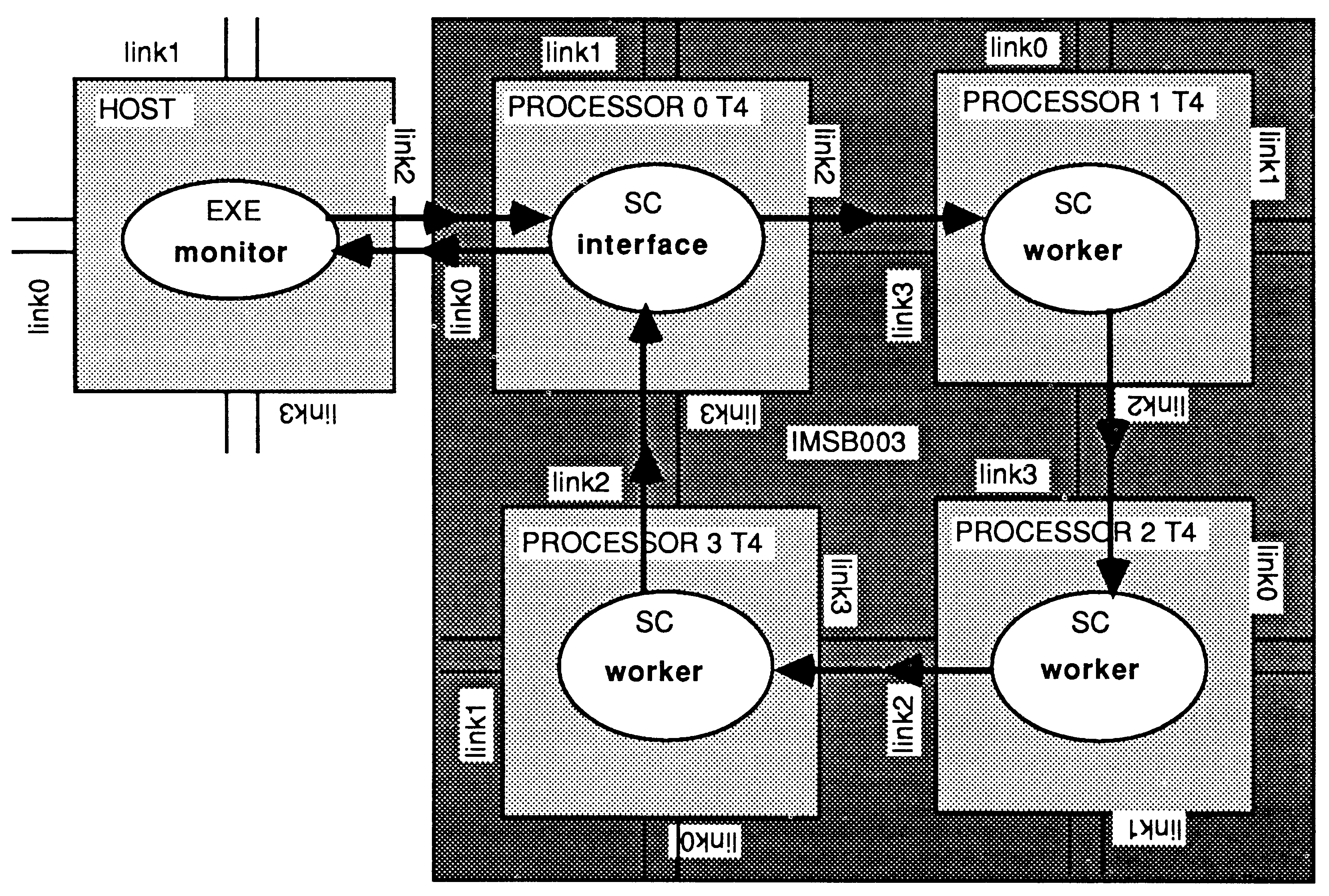
The configuration required for the IMSB003 is to map interface onto the first transputer, first because it is the first mentioned in the program, and to map worker onto all three remaining transputers.
|
|
{{{ configuration
CHAN OF ANY app.in, app.out: [number.of.transputers]CHAN OF ANY link: PLACED PAR PROCESSOR 0 T4 PLACE app.in AT link0in: PLACE app.out AT link0out: PLACE link[0] AT link2out: PLACE link[number.of.transputers - 1] AT link3in: interface (app.in, app.out, link[0], link[number.of.transputers - 1]) PLACED PAR i = 1 FOR (number.of.transputers - 1) PROCESSOR i T4 PLACE link[i - 1] AT link3in: PLACE link[i] AT link2out: worker (link[i - 1], link[i]) }}} |
The transputers are all running in parallel hence the configuration language expects the constructor PLACED PAR to denote PROCESSORS running in parallel. For the three worker processes a replicator has been used with index i having the values 1,2 and 3. All the transputers are of type T4.
The interface is connected to the host through app.in and app.out on link zero whilst the workers are connected to each other and to interface through the link two to link three connections provided with the IMSB003 board.
The following steps are now required, in the following order, to run the application as described above on an IMSB003.
There would be no reason to change this configuration if the target was only ever a single IMSB003. If more than one IMSB003 was used, as is available in an Inmos ITEM, then it would be better to configure around the number of IMSB003s used rather than the number of transputers.
This section takes the application code used before and looks at how this might be configured for running on a number of IMSB003 boards. For simplicity and compatibility with the earlier examples the algorithm is still implemented as a pipeline of processes.
#USE "header.tsr"
#USE "problem.tsr" {{{ extra constants for configuring for x transputers VAL number.of.B003s IS 4: -- must be greater than one VAL transputers.on.B003 IS 4: VAL number.of.transputers IS number.of.B003s * transputers.on.B003: VAL number.of.elements IS string.length: VAL elements.per.transputer IS number.of.elements/number.of.transputers: VAL remaining.elements IS number.of.elements - (elements.per.transputer * number.of.transputers): }}} PROC worker (CHAN OF letters in, out) VAL elements IS elements.per.transputer: [elements]CHAN OF letters pipe: PRI PAR PAR -- prioritise getting the links started element (in, pipe[0]) element (pipe[elements-2], out) PAR i = 0 FOR elements - 2 element (pipe[i], pipe[i+1]) : |
This is nearly the same code for the worker procedure as before. The difference is that the number of element processes is derived from the number of IMSB003 boards that are included in the network.
The constant number.of.B003s is now the root of the algorithm. Should the number of IMSB003s in the network be changed then a simple change of this constant and re-compilation/configuration will change the software to suit.
{{{ PROGRAM progx
{{{F progx.tsr ... SC PROC interface ... SC PROC worker ... link constants -- number of B003s must be greater than 1 and match value in SCs VAL number.of.B003s IS 4: {{{ configuration for x B003s [(number.of.B003s - 1) * 2]CHAN OF ANY connect: PLACED PAR ... first board in rack ... boards in middle of rack ... last board in rack }}} }}} }}} |
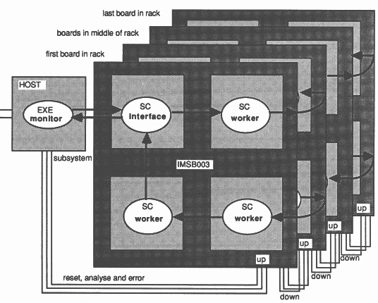
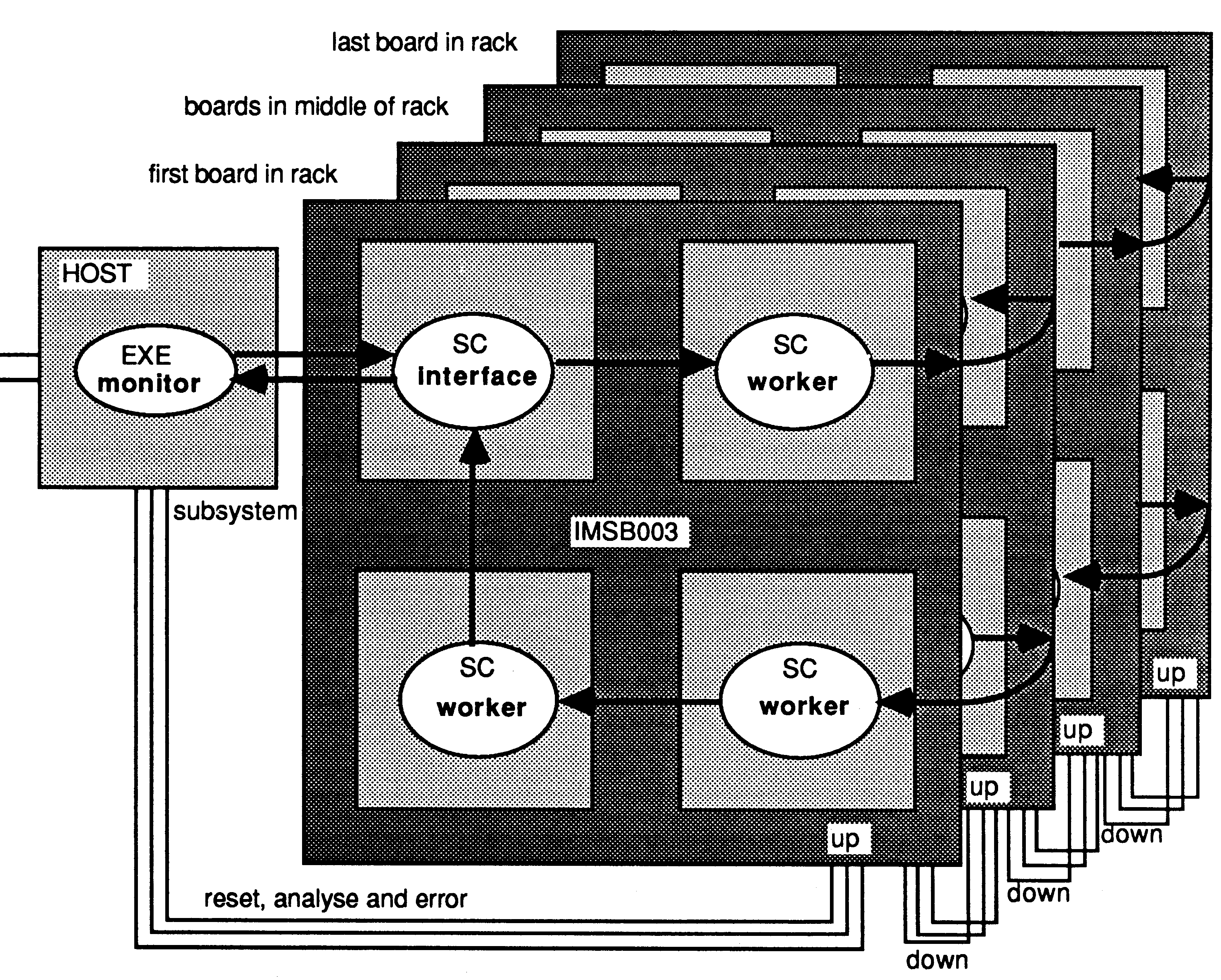
The structure of the PROGRAM now has configuration detail based on board level descriptions. The first board communicates with the host transputer, the boards in the middle of the rack have the same code and similar configuration whilst the last board must have a different configuration to terminate the pipeline. It is assumed that at least three IMSB003s will be involved or the configuration will have to be changed.
We can now look at the configuration used for each of these three types of board.
{{{ first board in rack
VAL board IS 0: CHAN OF ANY app.in, app.out: [3]CHAN OF ANY on.board: PLACED PAR PROCESSOR 0 T4 -- connection to host transputer PLACE app.in AT link0in: PLACE app.out AT link0out: PLACE on.board[0] AT link2out: PLACE on.board[2] AT link3in: interface (app.in, app.out, on.board[0], on.board[2]) PROCESSOR 1 T4 PLACE on.board[0] AT link3in: PLACE connect[(board*2)+0] AT link1out: worker (on.board[0], connect[(board*2)+0]) PROCESSOR 2 T4 PLACE connect((board*2)+1] AT link0in: PLACE on.board[1] AT link2out: worker (connect[(board*2)+1], on.board[1)) PROCESSOR 3 T4 PLACE on.board[1] AT link3in: PLACE on.board[2] AT link2out: worker (on.board[1], on.board[2]) }}} |
This configuration is for the first IMSB003 in the rack, quite often for simplicity, the one on the left hand end of a rack. The configuration is based around this board being numbered as board 0. The first transputer specified is the one connected to the host. This transputer must therefore run the interface process in order to communicate correctly with the monitor. The other three transputers on this board run the worker process. The channels in onboard are used to connect transputers on this board alone, the connect channels are mapped onto the links to the next board in the pipe.
{{{ boards in middle of rack
PLACED PAR board = 1 FOR number.of.B003s - 2 [2]CHAN OF ANY on.board: PLACED PAR PROCESSOR (board * 4) + 0 T4 PLACE connect[(board*2)-2] AT link0in: PLACE on.board[0] AT link2out: worker (connect[(board*2)-2], on.board[0]) PROCESSOR (board * 4) + 1 T4 PLACE on.board[0] AT link3in: PLACE connect[(board*2)+0] AT link1out: worker (on.board[0], connect[(board*2)+0]) PROCESSOR (board * 4) + 2 T4 PLACE connect[(board*2)+1] AT link0in: PLACE on.board[1] AT link2out: worker (connect[(board*2)+1], on.board[1]) PROCESSOR (board * 4) + 3 T4 PLACE on.board[1] AT link3in: PLACE connect[(board*2)-1] AT link1out: worker (on.board[1], connect[(board*2)-1]) }}} |
This configuration is replicated according to the number of IMSB003 boards available, remembering that two must become the first and last in the pipe. The same convention is used as before, the channels on.board are for connections between one transputer and another preconnected on the same IMSB003. The four connect channels connect this board with the previous and the next in the pipe. The communication path is circular so that data transfer is only ever in one direction on a single link.
{{{ last board in rack
VAL board IS number.of.B003s - 1: [3]CHAN OF ANY on.board: PLACED PAR PROCESSOR (board * 4) + 0 T4 PLACE connect[(board*2)-2] AT link0in: PLACE on.board[0] AT link2out: worker (connect[(board*2)-2], on.board[0]) PROCESSOR (board * 4) + 1 T4 PLACE on.board[0] AT link3in: PLACE on.board[1] AT link2out: worker (on.board[0], on.board[1]) PROCESSOR (board * 4) + 2 T4 PLACE on.board[1] AT link3in: PLACE on.board[2] AT link2out: worker (on.board[1], on.board[2]) PROCESSOR (board * 4) + 3 T4 PLACE on.board[2] AT link3in: PLACE connect[(board*2)-1] AT link1out: worker (on.board[2], connect[(board*2)-1]) }}} |
The last board uses one extra on.board channel to provide the connection between the outward data path and the return path as illustrated in the diagram below. All processors are running the same code, worker, except the one connected to the host running interface.
To run this example follow the same steps as in stage3 with the exception of the cables required. All the connect channels require link connections to be made from the host to the first IMSB003 and subsequently onto the other IMSB003s. The position of the cables can be double checked using the config info utility in the configurer toolset and the IMSB003 user manual supplied with the board. The reset, analyse and error connections should be made as below.
|
|
The first IMSB003 should be connected via the up port to the subsystem port of the host board, thus enabling the bad network utility to reset the transputers on this board before loading the code. These signals should be carried from the first board in the pipe on to all the others. This is achieved by connecting the down port from the first board to the up port of the second board and then subsequent ups to downs until all the boards are combined to appear as one subsystem to the host transputer. Thus when the network is loaded all the IMSB003 boards will be reset prior to the loading of the code for the complete target system,
[1] Transputer reference manual, Inmos Ltd Bristol
[2] Technical note 10: ”IMS 8003 Design of a multi-transputer board”, Abhay Vadher and Paul Walker, Inmos Ltd Bristol
[3] A tutorial introduction to occam programming, Dick Pountain and David May, McGraw-Hill Book Company 1987, ISBN 0-07-050606-X
[4] Inmos Spectrum, Inmos Ltd Bristol
[5] Technical note 17: ”Performance Maximisation”, Phil Atkin, Inmos Ltd Bristol
[6] Technical note 11: ”IMSB004 IBM PC add-in board”, Stephen Ghee, Inmos Ltd Bristol